1 power, 2 communications – Varec Driver Entry Terminal 8620 User Manual
Page 20
Wiring
12
Installation and Operations Manual
3.1.1
Power
To connect DC or AC power to the 8620, connect the power wires to the appropriate terminals
supplied with the 8620 DET.
Note Before connecting power wires to the 8620 DET, ensure that the power is switched
off and that the 8620 DET is correctly grounded.
AC Wiring
To connect the AC wiring, perform the following steps:
1. Connect the hot wire to the fuse holder as shown in Figure 3-1 on page 10.
2. Connect the neutral wire to the black terminal as shown in Figure 3-1 on page 10.
3. Connect the ground wire to the green/yellow terminal.
DC Wiring
To connect the DC wiring, perform the following steps:
1. Connect the 20 - 48 VDC positive wire to the bottom of the fuse holder as shown in
2. Connect the negative wire to black terminal as shown in Figure 3-2 on page 11.
3. Connect the ground wire to the green/yellow terminal.
3.1.2
Communications
RS-485 is the default setting used for Com 2 as shown in Figure 3-1 on page 10.
RS-422 and RS-485 Wiring — Com 2
Note Com 1, Com 3, and Com 4 are all standard RS-232 Ports. All communications ports
are standard DB-9 male connectors. Com 2 also supports RS-232 if properly con-
figured.
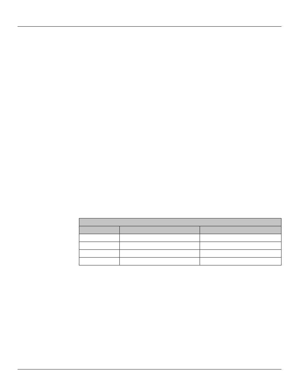
DB-9 Connector on I/O Bracket
Pin
Pin Name
Signal Type
1
422-RXD-
IN
2
422-RXD+
IN
3
485-422-TXD+
OUT
4
485-422-TXD-
OUT
Table 3-1:
4-Pin Connectors for RS-422 and RS-485 Communication Protocols