Package contents, Front and back panel front panel – M-AUDIO Biport 2x4s User Manual
Page 6
Package Contents
Included in the BiPort 2x4s package should be:
• The BiPort 2x4s interface unit.
• 8-pin Mini-DIN to DB-9 Serial cable for PC.
• 8-pin Mini-DIN to 8-pin Mini-DIN Serial cable for Mac.
• DC 9 volt, 500 mA power supply (US only).
• This instruction manual.
• A drivers, applications and diagnostics diskette for both Mac & PC.
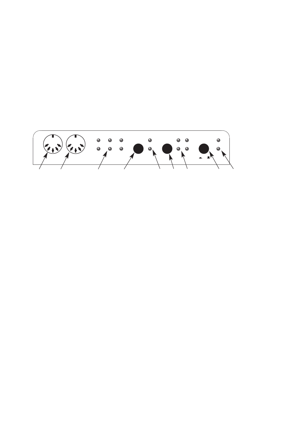
Front and Back Panel
Front Panel
1. MIDI In-A Connector - For MIDI Input channel A, the first MIDI
input of two.
2. MIDI Out-A Connector - For MIDI Output channel A, the first MIDI
output of four.
3. MIDI In and Out LEDs - Indicate MIDI Input and Output activity on
the 6 MIDI ports.
4. Write button - Starts and stops the SMPTE writer, sets the Write
Offset time.
5. “Locked” and “Writing” LEDs - The “Locked” LED indicates SMPTE
reader/regenerator status; the “Writing” LED indicates SMPTE
writer status.
6. Format button - Manually selects the format of SMPTE Output. Push
repeatedly until the proper format is set.
7. SMPTE Format LEDs - Indicate the current SMPTE output format.
“24” indicates 24 fps (frames per second), “25” indicates 25 fps, “DF”
indicates 30 fps drop-frame, and “30” indicates 30 fps or 29.97 fps in
special cases.
8. Mac Thru button - Selects whether host data is routed to the BiPort
circuitry, or instead by-passed directly to the Mac Thru port.
9. Mac/PC LEDs - Indicate whether the BiPort is connected to a Mac,
PC, or by-passed (Mac Thru).
In-A
24
Write
DF
30
25
Mac
Thru
PC
In-A
Locked
Writing
Format
Out-A
Out-A Out-C
In-B
Out-B Out-D
Thru MIDI
Mac
1
2
3
4
5
6
7
8
9
6