Setting up your snow thrower – Troy-Bilt 31AH9Q77766 User Manual
Page 7
7
3
Setting Up
Your Snow
Thrower
IMPORTANT
Prior to operating
your snow thrower,
refer to Auger Control
Test in the Operation
section. Read and
follow all instructions
carefully and perform
all adjustments to verify
your snow thrower is
operating safely and
properly.
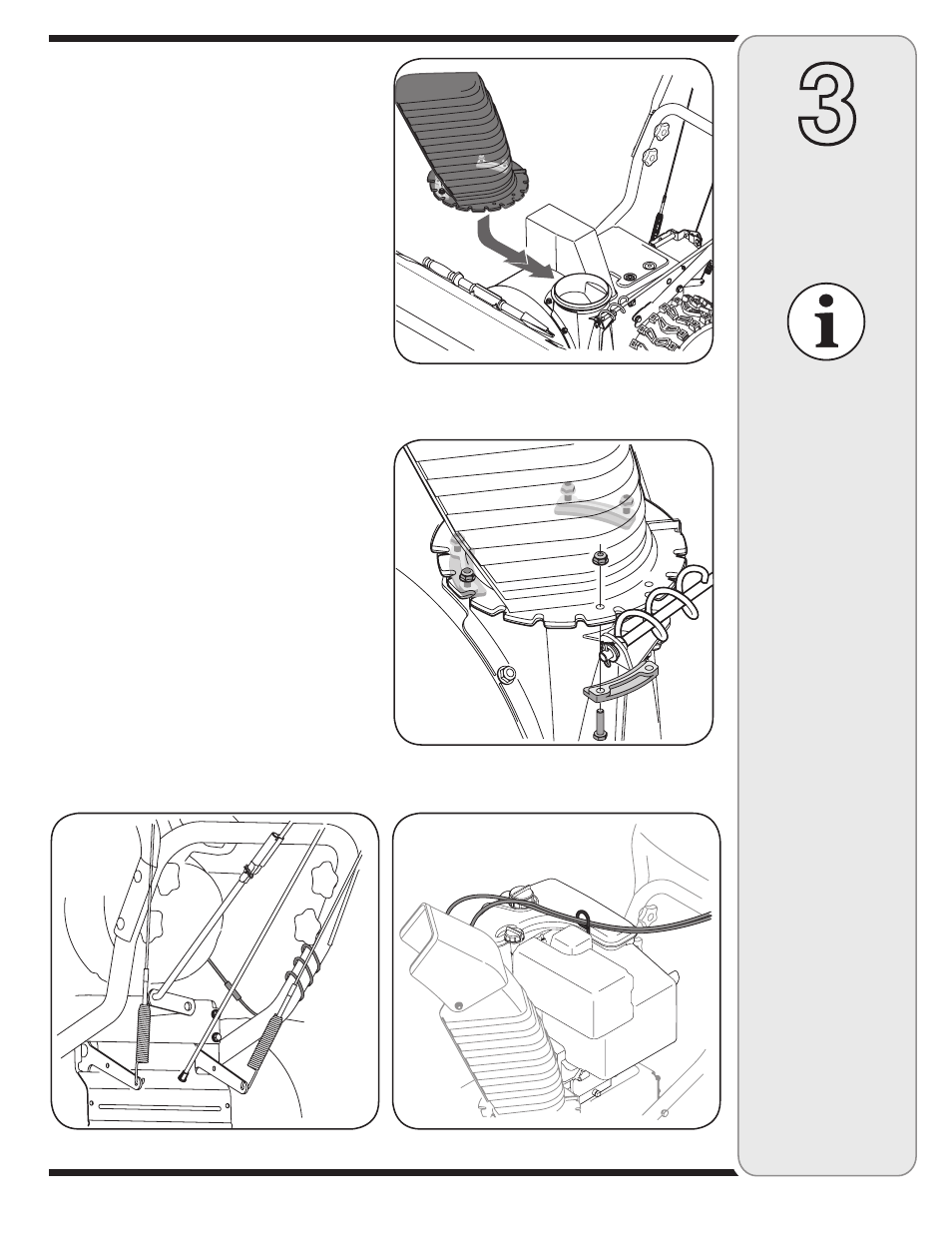
Figure 3-6
Figure 3-8
Figure 3-7
NOTE: If the full range of speeds (forward and reverse)
can not be achieved, refer to the “Making Adjustments”
section.
4. a. Remove the internal cotter pin from the upper chute
crank. Slide the upper chute crank into the sleeve
on the lower chute crank.
b. Align the hole in the upper chute crank with the
hole in the sleeve (If necessary, use a pair of pliers
to assist in aligning holes). Insert the internal cotter
pin through the holes to secure the chute crank.
See Figure 3-4.
5. Remove lock nuts and screws securing one of the
flange keepers to the chute assembly.
6. Place chute assembly onto chute base as shown in
Figure 3-5, making sure that the notches engage with
the spiral end of chute directional control.
7. Secure flange keeper removed earlier with lock nuts
and screws. Tighten down nuts securing the other two
flange keepers. See Figure 3-6.
8. If not already done, slip the cables that run from the
handle panel to the discharge chute into the cable
guide located on top of the engine. See Figure 3-7.
9. If not already done, wrap the wire of the head lamp
wire harness down the right handle until the wire can
be plugged into the engine alternator wire connector
down on the engine. See Figure 3-8.
10. Normally the cable ties holding the steering cables
against the handle are loosely installed on each side
of the lower handle at the factory. Pull the cable ties
tight to secure. Cut the excess from the ends of cable
ties.
The extension cord is fastened with a cable tie to the rear
of the auger housing for shipping purposes. Cut the cable
tie and remove it before operating the snow thrower.
Figure 3-5