Changing friction wheel – Troy-Bilt 4510 User Manual
Page 21
If also replacing the drive belt, proceed to the “Drive
11.
Belt” instruction. If not, reposition the transmission
frame back onto the auger housing. Install the drive
belt on the engine pulley, re-connect the auger cable
“Z” fitting and auger idler rod ferrule to the brake
bracket. Reposition and secure the engine pulley belt
guard, and re-install the belt cover.
NOTE:
Make sure to remove the piece of wood blocking the
impeller.
Check the auger drive belt adjustment. With the auger
clutch lever in the disengaged position, the top surface of
the new belt should be even with the outside diameter of
the pulley.
To adjust, disconnect ferrule from brake bracket assembly.
Thread ferrule in (towards idler) to increase tension on belt,
or out to decrease belt tension.
NOTE:
The brake puck must always be firmly seated in the
pulley groove when auger control is disengaged.
CAUTION:
Repeat the “Testing Auger Drive
Control” from the Assembly and Set-up section
before operating the snow thrower.
Drive Belt Replacement
If not already done, remove the auger drive belt from the
front pulley of the engine double pulley. Refer to “Auger
Belt Replacement” instructions in the previous sub-section.
Pull the idler pulley away from the backside of the drive
1.
belt to relieve the tension and slip the drive belt off the
idler pulley. Carefully release the idler pulley. See Figure
7-8.
Roll the drive belt off the lower drive pulley and then
2.
remove the belt from the engine pulley.
Install the new belt on the pulleys in the reverse order and
3.
re-tension with the idler pulley.
Reassemble by performing the previous steps in the
4.
opposite order and manner of removal.
Changing Friction Wheel
The rubber on the friction wheel is subject to wear and
should be checked periodically. Replace the friction wheel
if any signs of wear or cracking are found.
Drain the gasoline from the snow thrower, or run the
1.
fuel tank dry to prevent a hazardous situation.
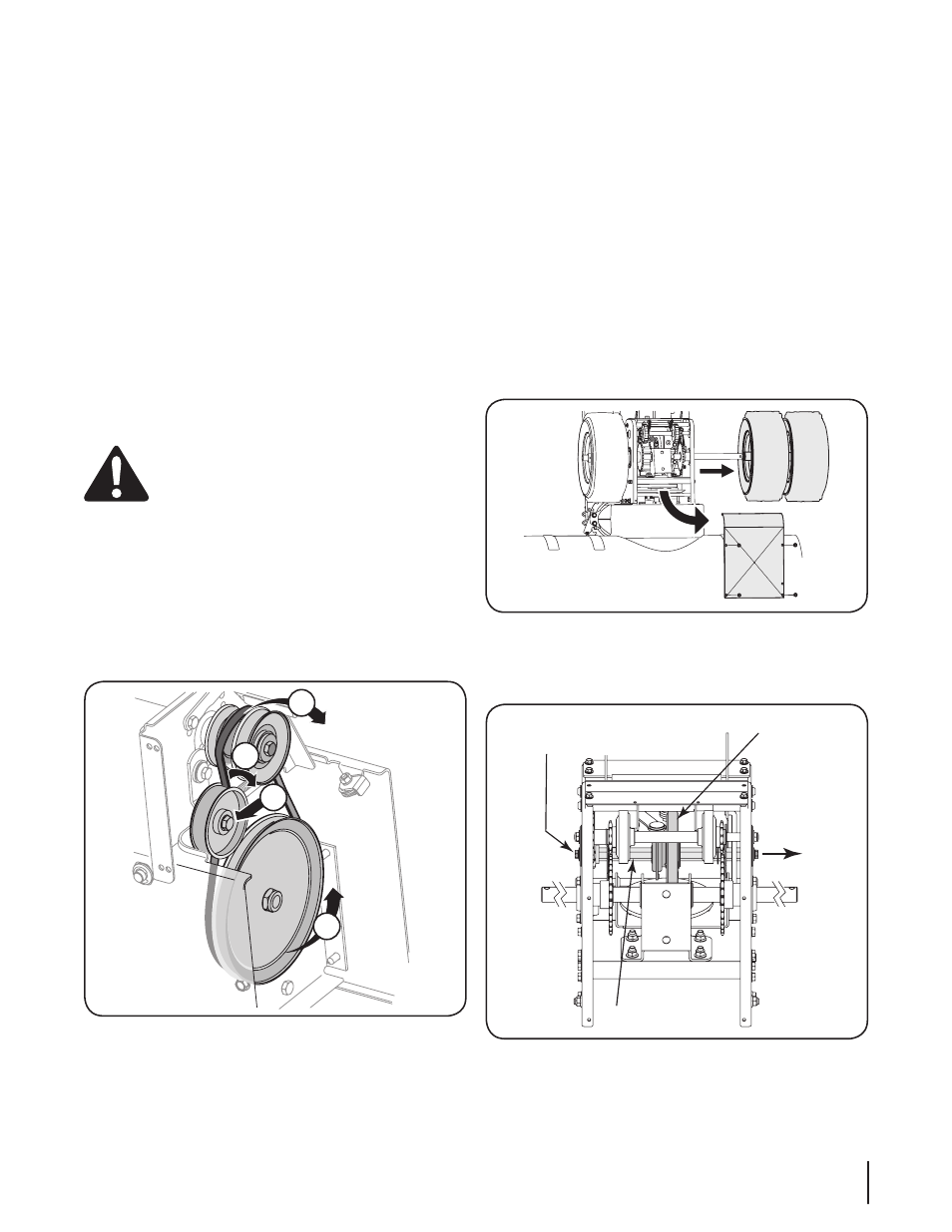
Tip the snow thrower up and forward, so that it rests on
2.
the housing.
Remove screws from the frame cover underneath the
3.
snow thrower (refer to Figure 7-9). Remove the right
wheels from the axle.
Using a 3/4” wrench, hold the hex shaft and remove the
4.
hex screw and belleville washer and bearing from left
side of the frame. Refer to Figure 7-10.
Figure 7-8
Figure 7-9
Figure 7-10
2
3
1a
1b
Remove Hex Screw
& Belleville Washer
Friction Wheel
Assembly
Hex Shaft
Slide Hex
Shaft Out
Right Side
21
s
ectiOn
7 — s
ervice