System - i/o page – TC electronic SDN BHD P2 User Manual
Page 22
SYSTEM - I/O PAGE
20
GPI Technical specifications
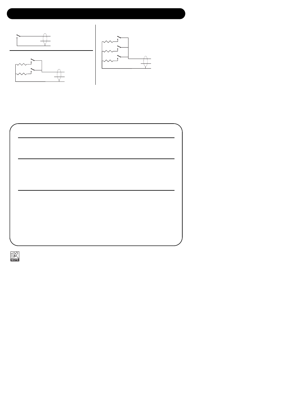
Inside the processor, a 10kohm resistor connects the Tip terminal to a +5V power supply. When
nothing is connected to the GPI input, the input voltage therefore is +5V. Resistors can be used to
pull down the voltage as suggested in Fig 1.
In Table 1, voltages outside the limits mentioned are to be considered invalid. No action is taken if
invalid measurements are made. GPI recall action resumes when a stable, valid measurement
again is detected.
Mode
1 of 2
1 of 4
1 of 8
Preset No
1
2
1
2
3
4
1
2
3
4
5
6
7
8
Target / Vs
1.000
0.000
1.000
0.687
0.545
0.438
1.000
0.824
0.687
0.600
0.545
0.489
0.437
0.400
Min typ / V
2.67
0.00
4.16
3.38
2.67
0.00
4.50
4.06
3.38
2.94
2.67
2.38
2.13
0.00
Target typ / V
5.00
0.00
5.00
3.44
2.73
2.19
5.00
4.12
3.44
3.00
2.73
2.44
2.19
2.00
Max typ / V
5.00
0.51
5.00
3.50
2.79
2.25
5.00
4.18
3.50
3.06
2.79
2.50
2.25
2.06
Rather than absolute voltage measurements, the windows are defined as a fraction of the
supply voltage, Vs. This voltage can be measured with a high impedance DMM on the Tip
terminal when no pull down resistors are applied.The table shows values as a fraction of Vs,
and, as a guideline, typical voltages when Vs=5.000V. (If the Supply voltage is e.g. 5.015V, the
table should be corrected by multiplying these values by 5.015/5).
bet ee 8 p esets
RL1
GPI Input
Select 1 of 2
RL1
off
preset 1
on
preset 2
tip
ring
sleeve
nc
RL1
RL2
GPI Input
Select 1 of 4
RL2
RL1
off
off
preset 1
off
on
preset 2
on
off
preset 3
on
on
preset 4
tip
ring
sleeve
R1, 12k
R2, 22k
nc
RL1
RL2
RL3
GPI Input
Select 1 of 8
RL3
RL2
RL1
off
off
off
preset 1
off
off
on
preset 2
off
on
off
preset 3
off
on
on
preset 4
on
off
off
preset 5
on
off
on
preset 6
on
on
off
preset 7
on
on
on
preset 8
tip
ring
sleeve
R1, 12k
R2, 22k
R3, 47k
nc