Installation – Tripp Lite B021-000-17 User Manual
Page 4
4
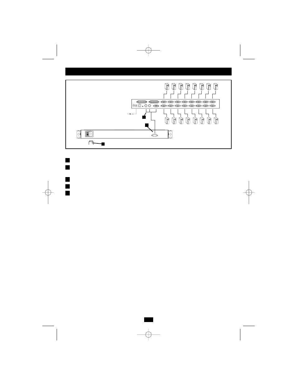
Refer to the example installation diagram below as you perform the following steps:
1. Plug the cable kit (provided with this unit) into the port on the B021-000 or B021-000-17.
2. Plug the keyboard, monitor, and mouse connectors on the other end of the cable kit into their
respective ports on the server or KVM.
3. Plug the power cord into the B021-000 or B021-000-17’s power socket and into an AC power source.
4. Power up your KVM installation.
5. Turn on the power to B021-000 or B021-000-17.
Note: The example diagram shows the B021-000 connecting to a B022-016 KVM switch. If you are
connecting to a different model, the console port connectors may be in a different location.
Installation
1
2
3
4
5
1
2
3
200510123 93-2493 B021-000 RM KVM Console OM.qxd 11/2/2005 1:52 PM Page 4
- IBAR12-20ULTRA (4 pages)
- 2-PORT COMPACT DVI USB B004-DUA2-K-R (1 page)
- WEXT5-B072-016 (2 pages)
- Network Dataline Surge Suppressors DHUB (12 pages)
- SVGA 1-to-4 Splitter B114-0H4 (5 pages)
- HDMI v1.3 Splitter B118-302-R (2 pages)
- TLM1015NC (3 pages)
- NETCOMMANDERTM B072-008-1 (24 pages)
- OmniSmart USB (13 pages)
- PM6NS (3 pages)
- HT706TSAT (4 pages)
- ISOBAR12ULTRA (4 pages)
- B006-004-R (19 pages)
- IBAR 12 (16 pages)
- 200401086 (3 pages)
- 602 (3 pages)
- SPS-615-HG (3 pages)
- B051-000 IP (65 pages)
- B004-008 (9 pages)
- ISOBLOK (12 pages)
- U215-004-R (8 pages)
- SUPER 10+TEL DELUXE (12 pages)
- B020-U08-19-K (8 pages)
- B119-302-R (3 pages)
- DB25-PAR (2 pages)
- P776-019 (2 pages)
- PK3021LI (2 pages)
- SRC-2X (19 pages)
- NC2004EC (2 pages)
- B020-008 (1 page)
- IP CAT5 B072-016-1-IP (32 pages)
- B064-032-04-IP (2 pages)
- IBRM 12/15A-L20P (4 pages)
- SmartPro USB (8 pages)
- DG206 (3 pages)
- Power Accessory Module PAM-3 (2 pages)
- DEU2TEL (2 pages)
- PK3022ET (2 pages)
- MT-6PLUS (4 pages)
- B022-004-R (13 pages)
- P036-002 (2 pages)
- B013-330 (3 pages)
- SUPER5DEU (3 pages)
- P772-015 (2 pages)
- TOUCHMASTER MT-6 (8 pages)