Block diagram – TOA Electronics P-9060DH User Manual
Page 13
13
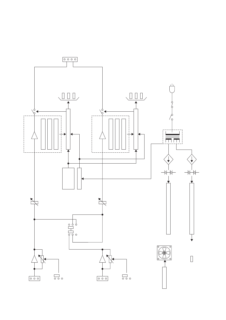
14. BLOCK DIAGRAM
VI Limiter
Offset Detector
Output Level Sensor
Protection Circuit
Power Supply for Power Amp. Unit
FAN Control
Heat Sink
Temperature
Sensor
Mute Control
Power Supply for Preamplifier
H
C
CH 1
10 kΩ
E
GAIN
Electronically balanced
VOLUME
CH 1 Power Amp. Unit
VOLUME
H
C
CH 2
10 kΩ
E
CH 1 70 V Line
SP OUT
(BTL)
(BTL)
CH 2 70 V Line
–20 dB
GAIN
0 dB
–20 dB
0 dB
Electronically balanced
CH 1 TO ALL
switch
CH 1/CH 2
PROTECT
POWER
PEAK
SIGNAL
VI Limiter
Offset Detector
Output Level Sensor
Protection Circuit
CH 2 Power Amp. Unit
PROTECT
PEAK
SIGNAL
–Vcc
+Vcc
PT
POWER
switch
120 V AC, 60 Hz
–Vcc
+Vcc
FAN
This manual is related to the following products: