3 system controls and connectors, 1 biooptix 10 front panel controls, 3 system controls and connectors -3 – Teledyne 10 User Manual
Page 15: 1 biooptix 10 front panel controls -3, 1 biooptix 10 front panel -3, 2 biooptix 10 front panel controls -3, Table 1-2 biooptix 10 front panel controls
BioOptix™ 10
Section 1 Introduction
1-3
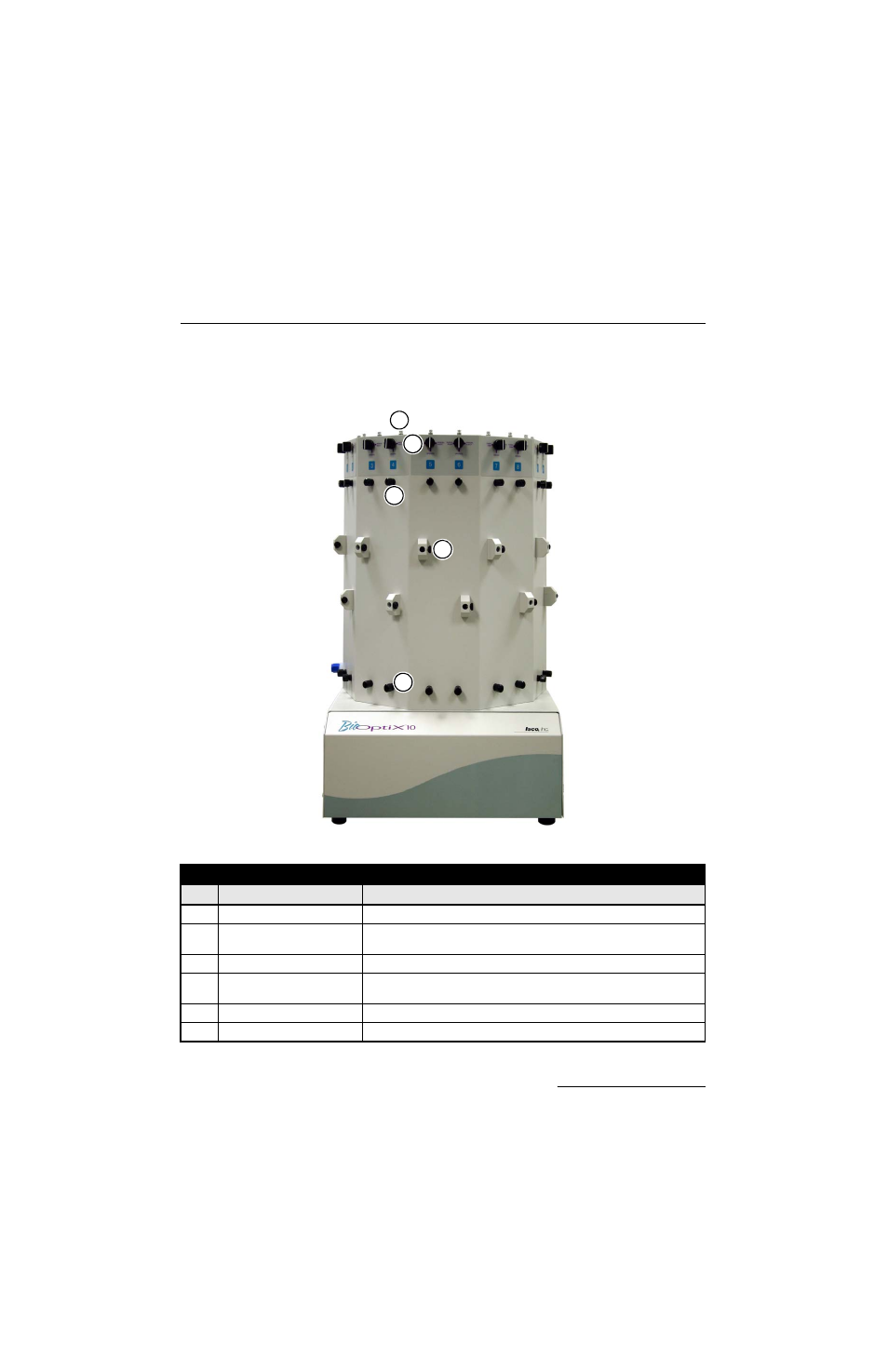
1.3 System Controls and
Connectors
1.3.1 BioOptix 10 Front
Panel Controls
Figure 1-1
BioOptix 10 front panel
1
3
4
5
2
Table 1-2 BioOptix 10 Front Panel Controls
Item Name
Description
1
Manual Sample Inject Port
Injection port for syringe-injected liquid samples.
2
Mode Knob
Configures fluid path for purging, manual sample injection, or purification
operation.
3
Column Inlet Port
Allows connection of tubing to column inlet.
4
Column Clamp Position Adjust Secures column clamp and allows for horizontal and rotational positioning of
columns.
5
Column Outlet Port
Allows connection of tubing from column outlet.
6
Column Clamp (Not shown)
Tightens to secure the chromatography column.