5 reference – Texas Instruments TPA751 MSOP User Manual
Page 16
Reference
2-6
Operation
2.5
Reference
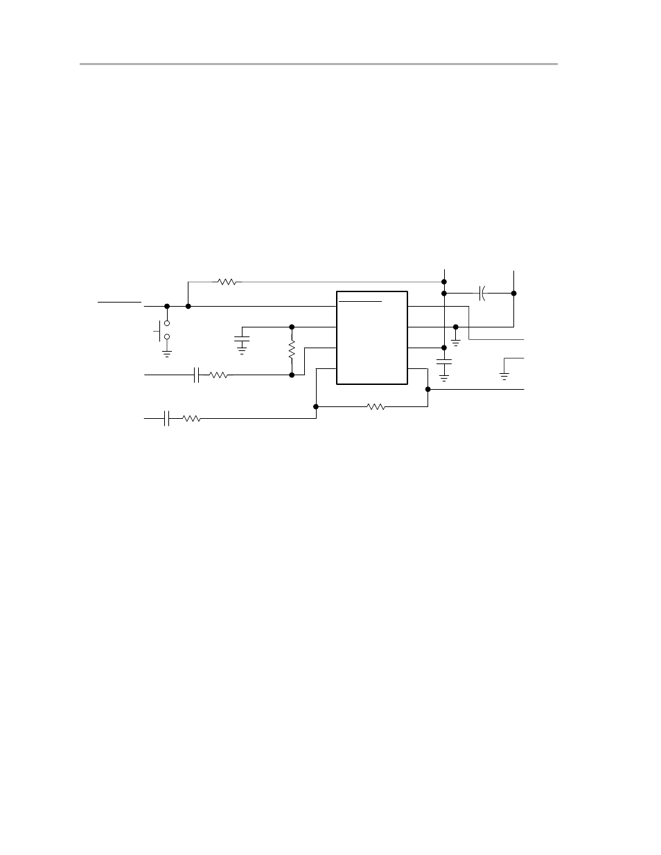
This section includes the TPA751 EVM schematic, the EVM parts list, and the
module PCB layers.
2.5.1
TPA751 EVM Schematic Diagram
Figure 2–4 shows the TPA751 EVM schematic.
Figure 2–4. TPA751 EVM Schematic Diagram
C1
1
µ
F
C3
1
µ
F
R1 20 k
Ω
IN–
Shutdown
S1
OUT–
GND
OUT+
R5
39 k
Ω
R4
20 k
Ω
NO
C4
10
µ
F
C5
1
µ
F
Shutdown
Bypass
In+
In–
V
O–
GND
V
DD
V
O+
8
7
6
5
1
2
3
4
GND
VDD
2.5 V to 5.5 V
+
C2
1
µ
F
IN+
R3
20 k
Ω
R2
39 k
Ω
TIATC
TPA751
See also other documents in the category Texas Instruments Receivers and Amplifiers:
- THS4151 (26 pages)
- TRF1500 (74 pages)
- SLOU082 (28 pages)
- TAS5508-5121K8EVM (24 pages)
- TPA6102A2 (16 pages)
- TPA3001D1EVM (22 pages)
- TPA6030A4 (25 pages)
- TPA701 (26 pages)
- TPA6110A2 MSOP (18 pages)
- TAS5727 (21 pages)
- THS4503EVM (28 pages)
- TPA005D02 (50 pages)
- SLOU121 (42 pages)
- TPA0243 (20 pages)
- TPA0253 (20 pages)
- TPA102 MSOP (26 pages)
- THS4131 (26 pages)
- SLOU020A (28 pages)
- TPA005D12 (44 pages)
- TPA6139A2 EVM (8 pages)
- TPA0103 (32 pages)
- SLOU106 (26 pages)
- THS4141 (26 pages)
- THS3001 (20 pages)
- TPA0233 (20 pages)
- TPA2008D2 (26 pages)
- 2004 (20 pages)
- TPA3003D2 (36 pages)
- SLAU081 (44 pages)
- TPA301 (28 pages)
- TPA3100D2 (11 pages)
- SLOU023A (26 pages)
- TAS5110D6REF (45 pages)
- TA5704EVM (27 pages)
- TAS5518 (20 pages)
- APA100 (42 pages)
- TPA3200D1 (30 pages)
- TAS5066PAG (22 pages)
- TPA6204A1 (16 pages)
- THS4150 (26 pages)
- TPA311 (28 pages)
- TPA3008D2 (31 pages)
- TPA6101A2 (16 pages)