Pressure control wiring – Sherwin-Williams ULTIMATE 824-032 User Manual
Page 19
824-033
19
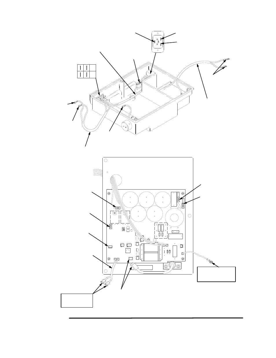
Pressure Control Wiring
7369A
Fig 17
Ground wire to
housing ground
From control
housing, WHITE
wire to L2
From control
housing, BLACK
wire to L1
From control housing,
one red wire to I1
From control housing,
one red wire to I2
Connector from
potentiometer to J3
Wires J4/J5 to
15/20 switch
Connector from pressure
transducer to J6
7169A
I1
I2
J3
J5 J4
J6
J7
GND
L1
L2
Twisted pair
GRN/YEL wire, E to housing ground
Housing ground
L
E
N
1
2
5
3
6
4
BLACK wire, L to on/off sw–1
WHITE wire, N to on/off sw–4
On/off sw
Twisted pair
Red wires to I1
and I2 on board
To J3
Twisted pair
WHITE
wire on/off
SW–5 to
to L2 on
board
BLACK
wire on/off
SW–2 to
to L1 on
board
Twisted pair
This manual is related to the following products: