Pressure control, Pressure control repair, Warning – Sherwin-Williams ULTIMATE 824-032 User Manual
Page 17
824-033
17
Pressure Control
7399A
7394A
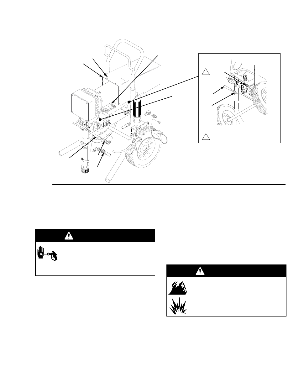
Fig 15
119
47
22,93
64
121
120
37
116
14
47
1
Seals (93) located inside conduit (22)
1
Pressure Control Repair
General Repair and Replacement
WARNING
INJECTION HAZARD
To reduce the risk of serious injury,
whenever you are instructed to relieve
pressure, follow the Pressure Relief
Procedure on page 7.
1.
Relieve pressure.
2.
Remove power cord (23) and plug retainer (23a)
by removing screws (230) and washers (229).
3.
Remove screws (213) and lockwashers (214).
Carefully remove control housing (202) from
control motor board (201) so internal wiring is not
damaged. Lay housing on side next to control
motor board. See Fig. 16 and parts list.
4.
Remove and replace only those components and
wires necessary for repair. Make a diagram show-
ing wire hook–ups for items removed to insure
correct wiring when reinstalling. See Fig 17 for
wiring information.
5.
Install control housing (202) to motor control
board (201) using screws (213) and
lockwashers (214).
Pressure Control Transducer and O–Ring
Replacement
WARNING
FIRE AND EXPLOSION HAZARD
Proper O–ring replacement is essential
to reduce the risk of fire or explosion
which can result in serious injury and
property damage. Also read FIRE OR
EXPLOSION HAZARD on page 4.
NOTE: Do not replace o–ring unless damaged or if
leakage is seen around weep hole, o–ring or
transducer.
1.
See Fig. 16 and pressure control part list. Disas-
semble pressure control as in steps 1 through 4 on
page 17 and remove old transducer (219) and, if
necessary, old o–ring (220).