TracRac SKU# 00-25850 User Manual
Page 3
6 Contractor Rac Pro
INSTRUCTION MANUAL
TracRac Inc. 994 Jefferson Street, Fall River, MA 02721-4893 • 800-501-1587
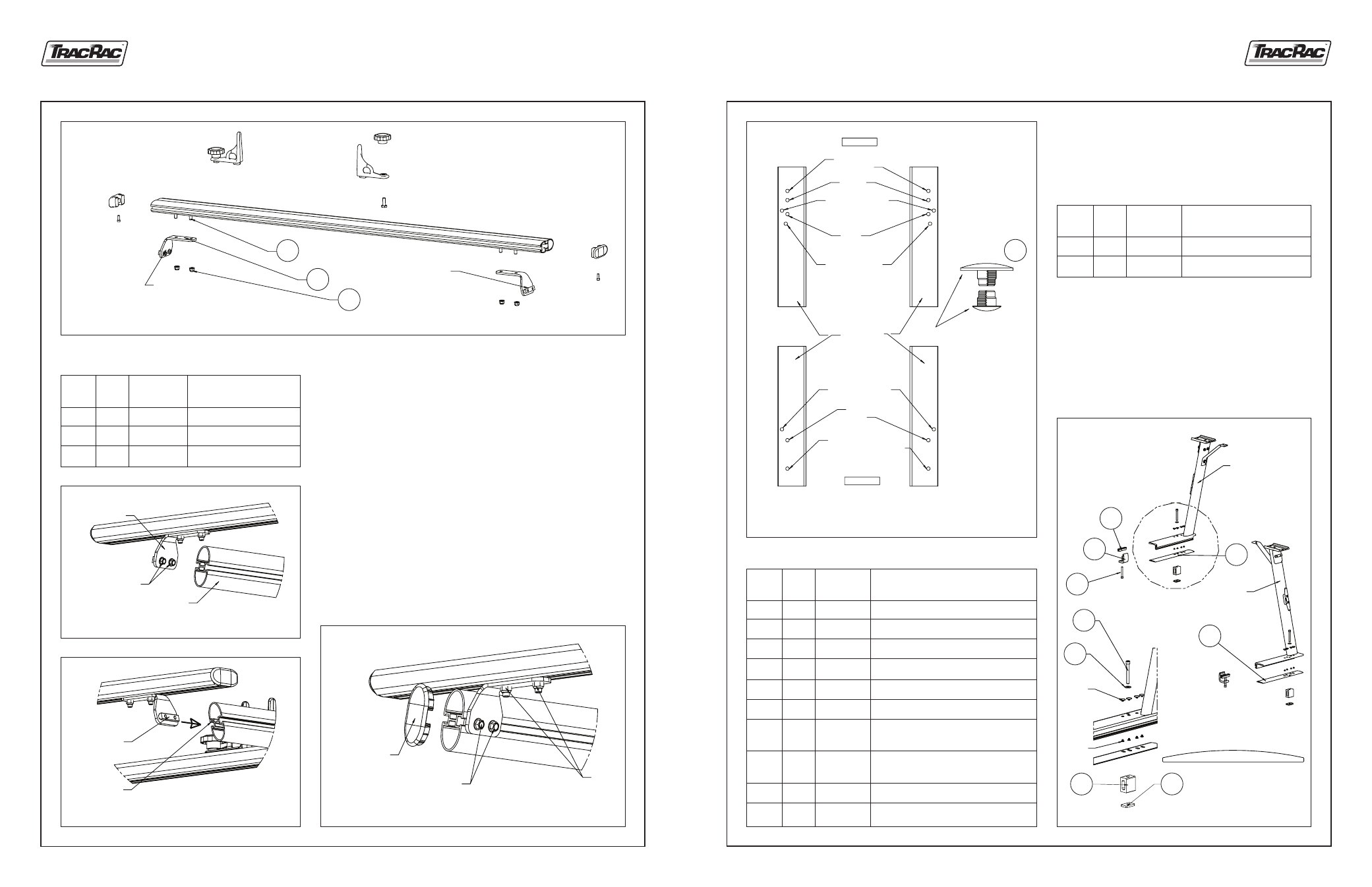
10. Built forward crossbar assembly by following the steps of the
standard crossbar assembly except slide 4 bolts (item 1) into
bottom groove of the crossbar (2 per side). Attach the end caps.
Loosely attach the bracket assemblies to the crossbar using lock
nuts and 15mm socket.
11. Loosen two bolts (13mm socket) on the forward bracket assemblies.
Slide the nut bar into the cantilever groove on each side.
12A. Align the bracket with the end of the front cantilever.
12B. Tighten two bolts using 13mm socket (Torque 90-110 lbs).
12C. Tighten two nuts using 15mm socket (Torque 220-240 lbs) on each side.
12D. Press the end caps into the front and rear cantilevers.
Make sure that all bolts and nuts are tightened up.
Assembly is completed.
Figure 10. Forward Crossbar assembly.
Item
No.
1
2
3
Qty.
4
2
4
Table 6. Forward Crossbar assembly parts
Description
T-Bolt, M10-1.5X25
Bracket, Forward
Lock Nut #10-1.5
Part No.
HD-80218
01-25051
HD-23179
Figure 11A. Crossbar installation. DETAIL A.
Figure 11B. Crossbar installation. DETAIL B.
Figure 12. End cap installation.
BRACKET
ASSMEBLY
1
BRACKET
ASSMEBLY
2
3
FORWARD
BRACKET
ASSMEBLY
TWO BOLTS
FRONT
CANTILEVER
NUT
BAR
CANTILEVER
GROOVE
TWO
BOLTS
TWO
NUTS
END CAP
P/N PI-23326
Contractor Rac Pro
INSTRUCTION MANUAL
3
TracRac Inc. 994 Jefferson Street, Fall River, MA 02721-4893 • 800-501-1587
3. After selecting the correct hole pattern for your truck
(using Figure 3), plug up all other holes using the black
plastic rivets. Large rivet–on the top, small rivet–on
the bottom (Figure 4).
Figure 3. Footprint for base of uprights.
Item
No.
1
2
Qty.
15
15
Table 3. Plastic Rivets
Description
Rivet, Small, Ratchet, Black
Rivet, Large, Ratchet, Black
Part No.
PI-23328
PI-23329
4. Attach rubber block assembly and rubber shim to uprights
using socket head cap bolt, washer, rubber shim, rubber
block and brass square pocket nut, see Figure 4. Complete
all four upright assemblies. Do not attach the L-Rail
clamps (items 1,9 and 10), see Figure 5. NOTE: Match
the hole patterns in the rubber shims to the correct
upright. Flat surface of rubber shim must face down.
Figure 4. Front upright
assembly.
Item
No.
1
2
3
4
5
6
7
8
9
10
Qty.
4
2
2
2
1
1
1
1
2
2
Table 4. Upright Assembly Parts
Description
Bolt Socket Head Cap, 3/8-16x3.00”
3/8 Washer, THIN
Rubber Block
Sq Pocket Nut, Brass
Rubber Shim, Front LH
Rubber Shim, Front RH
Rubber Shim, Rear LH
(Not Shown)
Rubber Shim, Rear RH
(Not Shown)
Clamp, L-Rail
U-Channel 3” Long
Part No.
HD-11011
HD-80078
RX-11031
01-2100N
FX-23269
FX-23270
FX-23271
FX-23272
01-23222
01-22911
FRONT
DODGE
FORD F150
CHEVY
TOYOTA TUNDRA
RH
GMC
FORD F250/350
UPRIGHT BASE
(VERTICAL OVAL TUBE
NOT SHOWN)
TOYOTA TUNDRA
DODGE
FORD F150/250/350
CHEVY
GMC
RH
REAR
LH
LH
SNAP IN THEM TOGETHER
UPRIGHT BASE BETWEEN
THEM NOT SHOWN
10
2
FRONT
UPRIGHT
LH
FRONT
UPRIGHT
RH
RUBBER SHIM
FLAT FACES DOWN
SMALL
RIVET
LARGE
RIVET
5
6
9
1
2
1
3
4