Installation, 3 networking the pdu, Continued) – Tripp Lite PDUMH20ATNET User Manual
Page 6
6
5-3
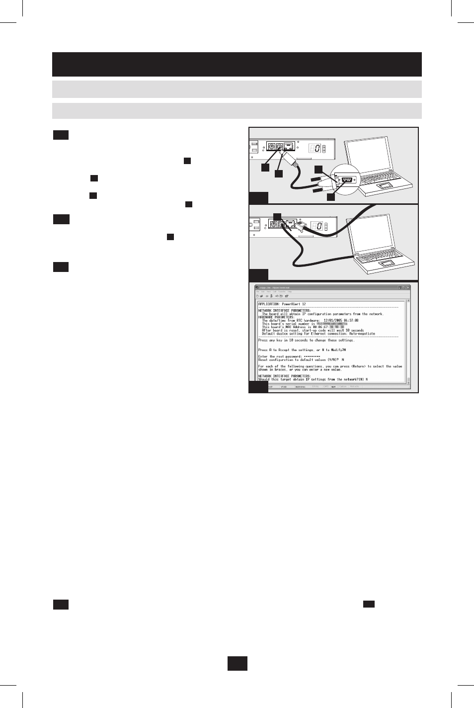
Connect PDU to Computer: Use the mini-
DIN to DB9 serial cable (part number 73-1025)
included with the PDU to connect the PDU to
the computer. The circular connector
A
at one
end of the cable attaches to the 8-pin mini-DIN
serial port
B
on the PDU. (Align the connector
carefully to avoid damaging the pins.) The DB9
connector
C
at the other end of the cable
connects to the computer's serial port
D
.
5-4
Connect PDU to Network: While the PDU
is powered, connect a standard Ethernet patch
cable to the RJ-45 Ethernet port
A
on the PDU.
Note: This port is not compatible with PoE (Power over Ethernet)
applications.
5-5
Configure PDU in Terminal Mode: After
a brief pause, an initialization page should appear
in the terminal emulation program. Press any key
on the keyboard within 10 seconds to change the
PDU settings. (If the 10-second period has
elapsed, you can reboot the PDU by powering
down completely and then restoring power.)
Follow the sequence of responses below in order
to assign an IP address to the PDU. The default
terminal mode root password is TrippLite.
Sample IP settings are shown - supply your own
IP information when you configure your PDU.
You can also change the root password, real-time clock and other settings. (Tripp Lite recommends
against changing the default settings unless you are an advanced user with a specific purpose.) After you
have finished entering settings, the PDU will save changes to memory and reboot (this may take several
minutes). After the PDU reboots, the initialization page should display the new static IP settings.
5-6
Remove Serial Cable: Remove the serial cable from the PDU and proceed to Step
6-1
.
Press A to Accept the settings, or M to Modify?
M
Enter the root password:
*********
Reset configuration to default values (Y/N)?
N
For each of the following questions, you can press
braces, or you can enter a new value.
NETWORK INTERFACE PARAMETERS:
Should this target obtain IP settings from the network?[N]
N
Static IP address [192.168.1.19]?
192.168.0.123
Static IP address is 192.168.0.123
Subnet Mask IP address [255.255.0.0]?
255.255.255.0
Subnet Mask IP address is 255.255.255.0
Gateway address IP address [192.168.1.1]?
192.168.0.1
Gateway address IP address is 192.168.0.1
5-5
5-3
5-4
A
B
C
D
A
2.3 Networking the PDU
(continued)
2.3.2 Static IP Address Assignment
(continued)
2. Installation
(continued)
English.indd 6
1/16/2009 4:37:23 PM