Installation, 1 mounting the pdu 2.2 connecting the pdu – Tripp Lite PDUMH20ATNET User Manual
Page 3
3
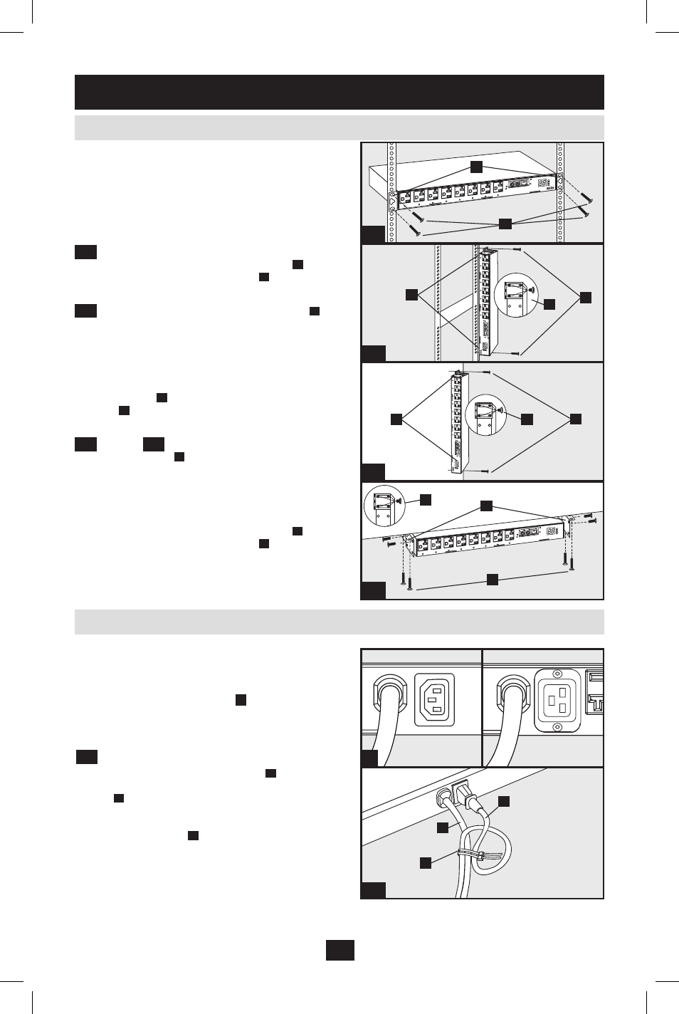
The PDU supports four primary mounting
configurations: 1U Rack, 0U Rack, Wall and
Under-Counter.
Note: Regardless of configuration, the user must determine the
fitness of hardware and procedures before mounting. The PDU
and included hardware are designed for common rack and rack
enclosure types and may not be appropriate for all applications.
Exact mounting configurations may vary.
1-1
1U Rack Mounting: Attach the PDU to the
rack by inserting four user-supplied screws
A
through the PDU mounting brackets
B
and into
the mounting holes of the rack rail as shown.
1-2
0U Rack Mounting: Remove the screws
C
attaching the mounting brackets to the PDU,
change the orientation of the brackets as shown
and reattach the brackets. Use only the screws
supplied by the manufacturer or their exact
equivalent (#6-32, 1/4" flat head). Attach the
PDU vertically by inserting two or more user-
supplied screws
A
through the PDU mounting
brackets
B
and into mounting points in the rack
or rack enclosure.
1-3
Wall or
1-4
Under-Counter Mounting:
Remove the screws
C
attaching the mounting
brackets to the PDU, change the orientation of the
brackets as shown and reattach the brackets. Use
only the screws supplied by the manufacturer or
their exact equivalent (#6-32, 1/4" flat head).
Attach the PDU to a stable mounting surface by
inserting two or more user-supplied screws
A
through the PDU mounting brackets
B
and into
secure points on the mounting surface.
1-1
1-2
1-3
1-4
A
B
B
A
B
C
B
B
C
C
A
A
A
C
2
PDUMH20AT
PDUMH20ATNET
PDUMH15AT
PDUMH15ATNET
The PDU includes two AC power inputs: Primary
and Secondary. The Primary input cord is
permanently attached to the rear of the PDU.
The Secondary input cord is detachable and
connects to the IEC power inlet
2
at the rear of
the PDU (PDUMH15AT,PDUMH15ATNET -
IEC-320-C14 inlet; PDUMH20AT,
PDUMH20ATNET - IEC-320-C20 inlet).
2-1
To connect the Secondary input cord:
Form a loop in the Secondary cord
1.
A
and
secure the juncture of that loop to the Primary
cord
B
with a zip tie. Be sure the zip tie is
secured around the Secondary and Primary
cords, as well as through the loop created in
the Secondary cord
C
. (See diagram). Note:
Give the cord as much slack as possible
between the loop and the cord’s outlet.
Once you’ve secured the two cords together
2.
and ensured that the Secondary cord has a
comfortable amount of slack, insert the
Secondary cord outlet into the IEC power inlet.
2-1
2. Installation
2.1 Mounting the PDU
2.2 Connecting the PDU
English.indd 3
1/16/2009 4:37:21 PM