Installation, Rack mounting – TOA Electronics BG-1120 User Manual
Page 13
13
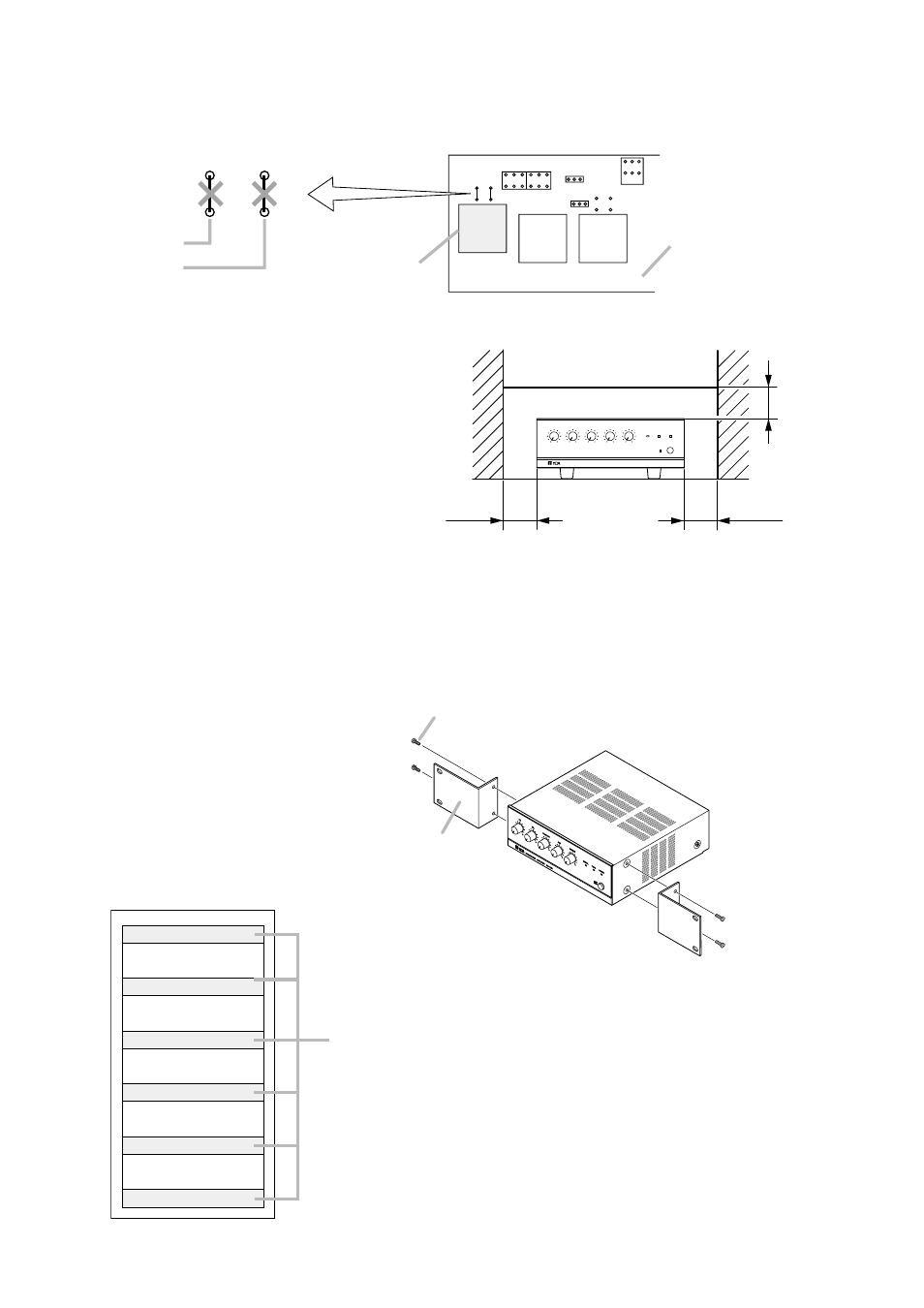
7.5.2. Program input
• Install an optional IT-453A Line Transformer in the specified location on the printed circuit board.
• Cut off the JP205 and JP206 jumper wires.
JP205
JP206
T202
T201
Preamplifier board
Line Transformer
IT-453A
8. INSTALLATION
Keep the unit's all sides at least 10 cm away from
objects that may obstruct air flow to prevent the
unit's temperature from rising.
At least
10 cm
At least
10 cm
At least
10 cm
INTEGRATED AMPLIFIER BG-1120
PROGRAM
10
0
TEL
0
10
0
MIC
10
10
0
0
10
AUX
MODULE
SIGNAL
OFF
POWER
PEAK
ON
9. RACK MOUNTING
To mount the amplifier in a standard 19" equipment rack, use the optional MB-1000 Rack Mouting Kit.
Attach the MB-1000 to the amplifier using the supplied 4 screws. When using other screws, ensure that each
screw is shorter than 16 mm.
Amplifier
Amplifier
Amplifier
Amplifier
Amplifier
PF-511 Perforated Panel (1-unit size)
Note
Mount the Perforated Panel PF-511 above and below each amplifier
for ventilation inside the rack.
About the perforated panel, consult your TOA dealer.
MB-1000
M4 x 16 Machine screw included in MB-1000