Texas Instruments XIO3130 EVM User Manual
Page 4
Hot-Plug-Mode Operation
www.ti.com
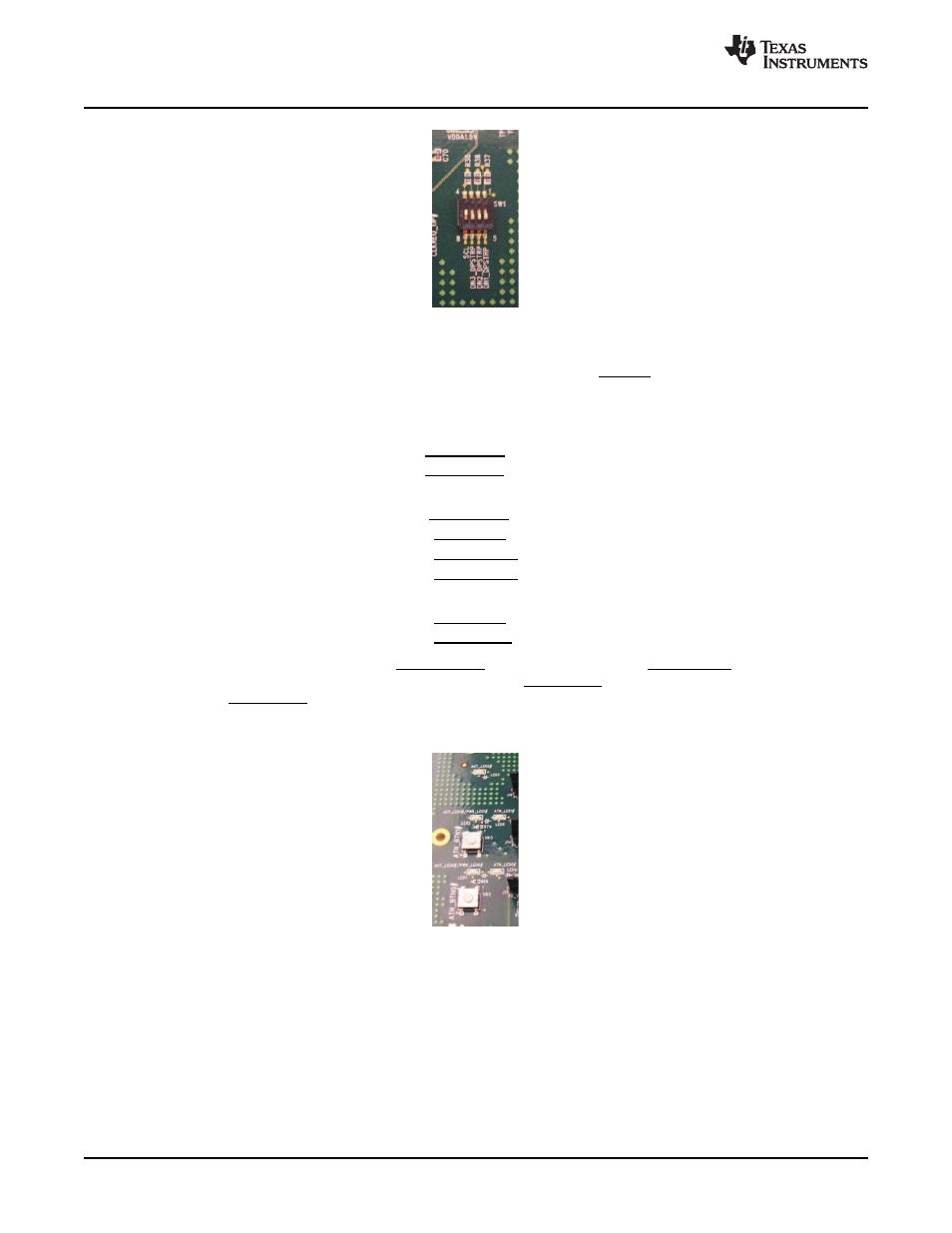
Figure 1-6. Dipswitch Configuration
The EEPROM (U3) should be reconfigured for hot-plug-mode operation. See
for an
explanation of how to configure the EEPROM. Upon deassertion of PERST, the XIO3130 automatically
reads data from the EEPROM. This data is used to preset various PCI configuration register bits. For
hot-plug-mode operation, the data in the EEPROM configures bits in the following registers:
•
GPIO B control register (PCI Register offset: BEh in upstream bridge)
–
PCIE_GPIO8_CTL = 010b – Port 1 ACT_BTN0
–
PCIE_GPIO9_CTL = 100b – Port 1 ATN_LED0
•
GPIO C control register (PCI register offset: C0h in upstream bridge)
–
PCIE_GPIO10_CTL = 011b –Port 2 ACT_BTN1
–
PCIE_GPIO11_CTL = 101b – Port 2 PWRFLT1
–
PCIE_GPIO12_CTL = 101b – Port 1 PWR_LED0
–
PCIE_GPIO13_CTL = 110b – Port 2 PWR_LED1
•
GPIO D control register (PCI register offset: C2h in upstream bridge)
–
PCIE_GPIO15_CTL = 101b – Port 1 PWRFLT0
–
PCIE_GPIO16_CTL = 011b – Port 2 ATN_LED1
Setting these bits configures LED1 as PWR_LED0 for port 1 and LED2 as PWR_LED1 for port 2. LED3 is
not used in hot-plug mode. LEDs 4 will be configured as ATN_LED0 for port 1 and LED5 will be
configured as ATN_LED1 for port 2. Push-button switch SW2 is the attention button for port 1 and SW3 is
the attention button for port 2.
Figure 1-7. GPIO Control Register
4
XIO3130 EVM
SLLU108 – July 2008