Hardware setup – Tripp Lite NETDIRECTORTM B064-016-02-IPG User Manual
Page 2
2
1. Hardware Setup
The KVM switch can be mounted in a 19-in (1U) rack. The rack mount brackets can be installed on either the front or the back of the
unit so that it can be mounted to the front or back of the rack.
1. Depending on whether you front-rack mount or rear-rack mount the unit, remove the two screws located on both sides of the front or
back of the unit.
2. Use the screws supplied with the rack mount kit to attach the rack mount brackets to the front or rear of the unit.
3. Position the device in the front or rear of the rack and align the holes in the mount brackets with the holes in the rack.
4. Secure the rack mount brackets to the rack using user-supplied screws.
In a single-stage installation, there are no additional KVM switches cascaded or daisy-chained from the B064-Series KVM. To set up a
single-stage installation, refer to the following instructions and the corresponding installation diagrams.
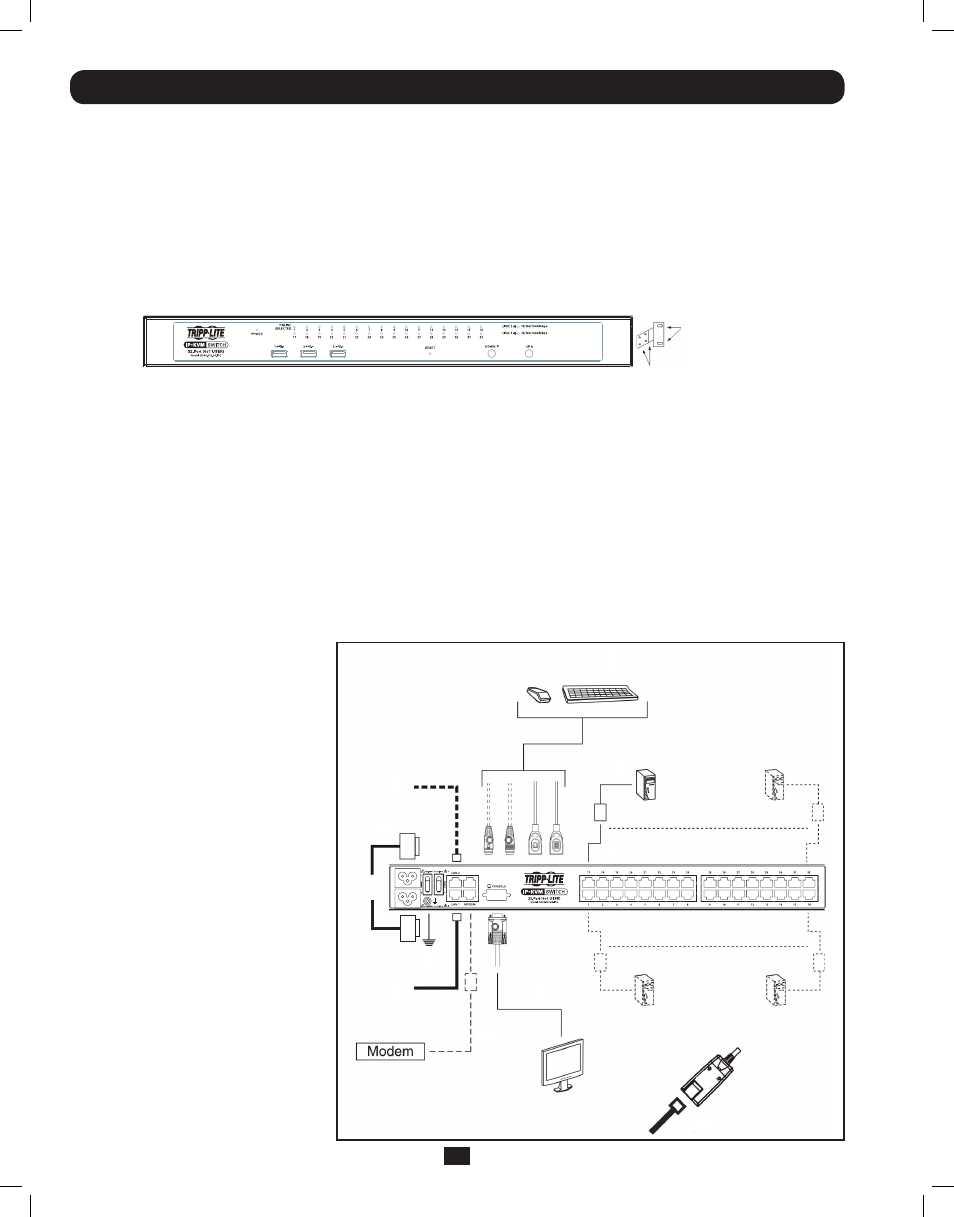
1. Make sure that power to all the devices you will be connecting, including all pre-existing devices on the installation, have been turned off.
2. Optional: Plug your Local Console’s keyboard, monitor, and mouse into the KVM’s Local Console Ports. You will need to connect the
included USB – PS/2 Console Cable Kit to the console port on the back of the unit.
Note: You can use any combination of keyboard and mouse connections. For example, you can use a PS/2 keyboard with a USB mouse.
USB keyboards and mice can plug into the USB ports on the front panel, as well as the ports on the USB – PS/2 Console Cable Kit. The
B064-Series KVM Switch does not support distances above 65 ft between the KVM and the local monitor.
3. Use Cat5e cable to connect any available KVM port to a Server Interface Unit (SIU): B055-001-PS2 (PS/2), B055-001-SER (Serial),
B055-001-USB (USB) or B055-001-USB-V2 (USB withe Virtual Media).
1.1 Rack Mounting
1.2 Single-Stage Installation
4. Connect the Server Interface Unit to the
computer/server.
5. Repeat steps 3 and 4 for each computer/
server you are connecting.
6. Connect a Cat5e cable from the network
into the KVM switch’s primary network
port (LAN 1).
7. Optional: Connect a second Cat5e cable
from the network into the KVM switch’s
backup (secondary) network port (LAN 2).
8. Optional Dial-In Modem Connection:
Use Cat5e cable to connect the KVM
switch’s Modem port to the included
RJ45 to DB9 Adapter, and connect the
adapter’s DB9 connector to the modem’s
DB9 port.
9. Use the included grounding wire to ground
the unit. Connect one end of the wire to
the grounding terminal, and the other end
of the wire to a suitable grounded object.
10. Plug the included power cords into the
KVM switch’s Power Sockets, and then
into a Tripp Lite Surge Suppressor,
Uninterruptible Power Supply (UPS) or
PDU.
11. Turn on the power to the KVM switch.
Once it is powered up, turn on the power
to the connected computers.
Use the M3x8 Phillips head hex screws
provided with the rack mount kit
Use user supplied
hardware to attach
to the rack
2
4
7
10
9
6
8
2
3
3
201107009 93-2913.indd 2
7/18/2011 2:57:59 PM