Instructions for reversing air flow (cont'd), Suspending or mounting the furnace, Suspending the furnace – Thomas & Betts EEDU User Manual
Page 6: Mounting the furnace
Form 421, Page 6
6. Instructions for Reversing Air
Flow (cont'd)
3. All Models - Relocate the limit control.
a) At the discharge end on the same side of the heat exchanger, mea-
sure down 4-1/2" and in 1-11/16". Using that point as the center,
punch a 2-1/4" diameter hole in the side panel.
NOTE: It may be necessary to move cable connections. Re-insert
screws to plug all holes in the side panel. After the limit control is
installed, the cable connections may be re-attached using field-sup-
plied sheet metal screws.
b) With the limit control on the heat exchanger side of the bracket,
slide the limit control/bracket assembly into the hole. Attach the
bracket with two sheet metal screws.
c) Cover all of the original factory-made limit control holes with a
field-supplied sheet metal plate. Do not leave any open holes in the
side panel or the heat exchanger bottom.
4. The furnace is now ready for installation with the air flow from front
to rear (gas valve side).
7. Suspending or Mounting the
Furnace
Before installing the furnace, check the supporting structure to be used
to verify that it has sufficient load-carrying capacity to support the weight
of the unit.
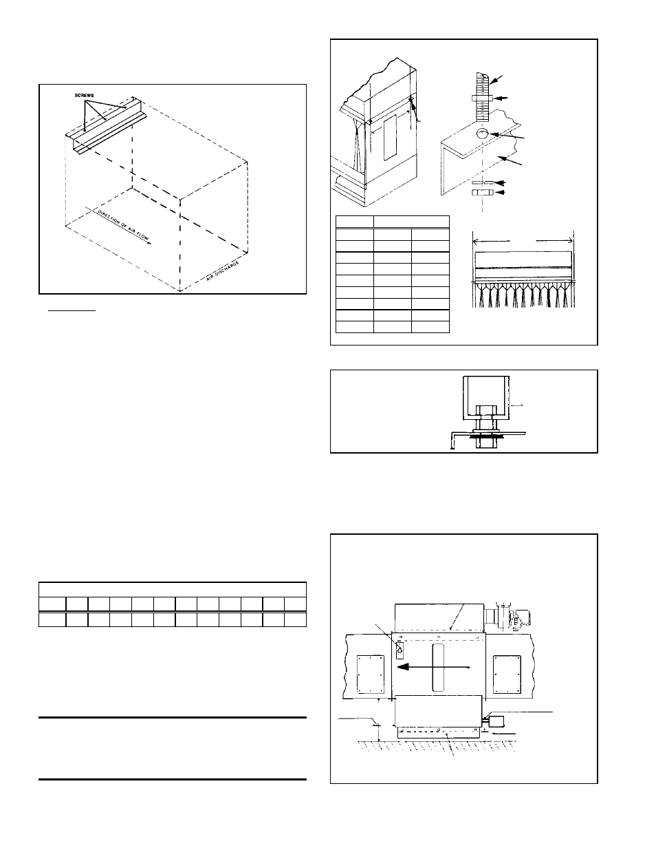
Suspending the Furnace
The furnace is provided with four 15/32" diameter holes to provide
four-point suspension. To suspend the unit, cut lengths of 7/16"-16
threaded rod to provide unit height. See Figure 4A for details. NOTE:
A hanger adapter kit Option CK3 is available to facilitate suspension.
See Figure 4B.
WARNING: Units must be level for proper
operation. Do not place or add additional weight
to the suspended furnace. See Hazard Levels,
page 2.
Figure 4B - Option
CK3 Hanger Kit (P/N
57959) with four
threaded sockets
Mounting the Furnace
Change position of the hanger bracket as shown in Figure 5. When the
furnace is mounted on combustible material, a minimum clearance of
12" is required.
Figure 5 - Base Mounted Furnace
Figure 3C - Model
HEEDU has only a
top rear heat
exchanger baffle.
Net Weight
S ize
75 100 125 140 170 200 225 250 300 350 400
Lbs
104 104 126 128 150 172 194 216 262 306 328
Figure 4A - Suspending a Single Furnace
Size
"A"
75-100
14-5/8"
371mm
125-140
17-3/8"
371mm
170
20-1/8"
371mm
200
22-7/8"
371mm
225
25-5/8"
371mm
250
28-3/8"
371mm
300
33-7/8"
860mm
350
39-3/8"
1000mm
400
44-7/8"
1140mm
16"
15/32"
(12mm)
Diameter
Hole
7/16" Diameter
Threaded Rod
Nut for 7/16" Rod
15/32" (12mm)
Diameter Hole
Hanger
Nut for 7/16" Rod
Split Ring Lockwasher
(406
mm)
A
Centerline of hangers
Free-turning
threaded
socket
(1" pipe)
As shipped location of hanger
support angle
Limit
Control
Access
Panel
Access
Panel
10"
(254
mm)
Combustion
Air Inlet
6" (152mm)
minimum
clearance
6"
Hanger Support Angle
Combustion Air Inlet
Keep clean and maintain 29"
(737mm) clearance for burner
rack service
12" (305mm)
Airflow
Direction