12 431m - mbs cabinet installation guide, 1 431m maintenance bypass switch (mbs) options – Toshiba AUXILIARY CABINET 431M User Manual
Page 47
39
4300 Series Ancillary Cabinets Installation and Operation Manual
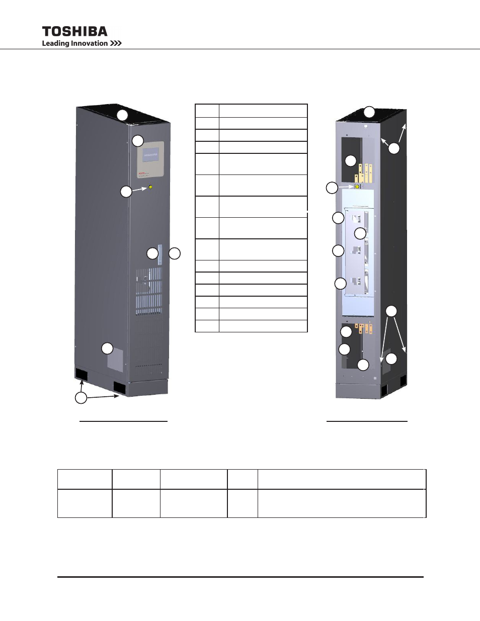
12 431M - MBS Cabinet Installation Guide
No.
Part
1
Toshiba Label
2
UPS On-Line Indicator
3
Door Latch
4
Door Lock-Out/Tag-Out
Hasp
5
Top Cable Access
Plate
6
Side Cable Access
Plates
7
Bottom Cable Access
Plate (Not Shown)
8
Cabinet Mate-up Points
(4 per Side)
9
MBS Bus Stubs
10
Interlock Plate
11
CB1
12
CB2
13
CB3
14
Forklift Access
12.1 431M Maintenance Bypass Switch (MBS) Options
(
All cabinets are O’Brien Black (Textured))
MBS Cabinet
Part Number*
UPS
Capacity
Operating Voltage
# of
Brkers
Safety Interlock
431M-
300 – 30 kVA
500 – 50 kVA
-F – 208/120 V
3
MS – Mechanical Interlock (Slide Bar) with Sole-
noid Release Unit. (Note: The solenoid locks the
slide bar in
Example:
431M500-F3MS is a floor-mount, 50kVA, 208/120V, Maintenance Bypass Switch with Slide-bar
Mechanical Interlock.
Figure 12-1 and Figure 12-2 show the external and internal components of the 431M.
431M - Door Closed
431M - Door Open
(Dead Fronts Removed)
7
4
6
5
3
8
10
2
11
12
9
5
6
6
1
8
9
13
14
Figure 12-1 - 431M Parts
Identification
2