TOA Electronics CUSTOM SERIES CR-3835L User Manual
Page 18
NOTE: DIAGRAMS & ILLUSTRATIONS NOT TO SCALE.
18
These fireplaces may sit directly on a com-
bustible surface. A 2" air space is required
between combustible framing and the chim-
ney. A 1" air space is required between com-
bustible framing and fireplace outer wrapper.
Combustible mantels and trim may be in-
stalled 12" above the fireplace opening as per
NFPA 211, Section 7-2.3.3. and
Figure 42. If
a mantel is of a noncombustible material, it is
exempt from these requirements as long as it
does not interfere with the installation or
operation of glass doors.
Figure 43
Figure 44
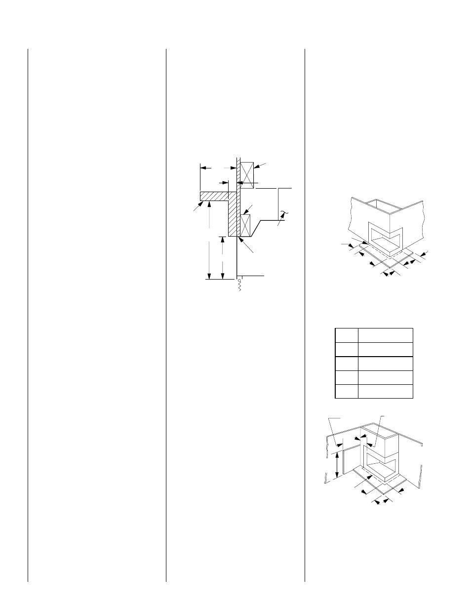
Hearth Extensions and Wall Shields
A hearth extension must be installed with
all fireplaces. It is to protect the combustible
floor in front of the fireplace from both radiant
heat and sparks. The hearth extension must
extend 8" beyond both sides of the fireplace
opening and 16" beyond the front (
Figure 43 ).
Use a hearth extension constructed of a durable
noncombustible material having an equal or
greater insulating value of k = 1.28BTU/IN FT
2
HR
°
F or a thermal resistance that equals or
exceeds r = .78 HR
°
F FT
2
IN/BTU. With these
values, determine the minimum thickness/ma-
terial required using the formula and the Table
on page 17.
Note: Any noncombustible material whose k
value is less than 1.28 or whose r value is more
than .78 is acceptable.
Figure 42
Typical Installation
*Both Of These Dimensions Must Be At Least 18”
When An Unvented Gas Log Set Rated At 26,000
BTU Or Higher Is Used. (Maximum 40,000 BTU)
12"*
Min.
8 3/8"*
Fireplace
Opening
Combustible
Mantel
and Trim
12"
Max.
1 1/2"
Finished
Wall
False
Header
Header
Spacer
If the fireplace is installed on a combustible
floor, use the metal safety strips (provided) on
the floor extending half under the fireplace and
half under the hearth extension (refer to
Figures
6 and 7 ).
A wall shield is required where a continuous
perpendicular side wall is within 12" of the
fireplace opening, (
Figure 44 ). Use a 24" W x
30" H wall shield constructed of millboard or a
durable, noncombustible material having an
equal or greater insulating value than K = .54BTU/
IN FT
2
HR
°
F. At no time may a perpendicular
side wall be closer than 8".
If fireplace is installed diagonally across a 90
°
corner; no wall shields are required.
Glass Doors
If glass doors are to be installed on these
fireplaces, refer to specific installation instruc-
tions packed with the glass doors. Use only the
doors that are listed for use with these fire-
places. Use of other non-listed glass door on
these fireplaces may constitute a potential fire
hazard and is not recommended.
CAUTION: CERTAIN GLASS DOORS OVERLAP
THE BLACK METAL FACING OF THE FIRE-
PLACE. IF THE FIREPLACE HAS BEEN FACED
WITH NONCOMBUSTIBLE MATERIALS, THERE
MIGHT NOT BE SUFFICIENT CLEARANCE TO
INSTALL THE GLASS DOORS OF YOUR
CHOICE. ENSURE ADEQUATE CLEARANCE IS
MAINTAINED AT ALL TIMES SO AS NOT TO
INTERFERE WITH THE INSTALLATION AND
OPERATION OF GLASS DOORS.
COLD CLIMATE INSULATION
If you live in a cold climate, it is especially
important to seal all cracks around the fire-
place opening with noncombustible material
and wherever cold air could enter the room.
Surrounding materials must be caulked where
it meets the black metal facing of the fireplace
to avoid cold air intrusion. Use noncombus-
tible caulking material only on fireplace facing
to seal. Also, the outside air inlet duct should
be wrapped with noncombustible insulation to
minimize the formation of condensation. Do
not place insulation materials on top of fire-
place or against chimney sections.
Note: A 2" air space must be preserved for all
combustible materials extending for any con-
tinuous length adjacent to the chimney.
It is especially important to insulate between
the studs of an outside chase cavity and under
the floor if the floor is above ground level. Do
not place insulation directly against the fire-
place or chimney system.
FIREPLACE FINISHES
Mantels and Trim
It is sometimes best to frame your fireplace
after it is positioned and the chimney is in-
stalled. Frame enclosure for chimney and fire-
place with 2 x 4’s (or heavier) lumber.
Note: The header may rest on the two (2) metal
top spacers on top of the unit but the header
must not be notched to fit around the spacers.
8"
(203mm)
20"
(508mm)
12"
(305mm)
Min.
Outside Corner
Metal Safety Strip
20"
(508mm)
D
B
A
C
E
20"
(508mm)
Inside Corner
If Less Than 12"
(305mm) Wall
Shield Required
20"
(508mm)
40"
(1016mm)
Wall
Shield
40"
(1016mm)
Metal Safety
Strip
Wall Shield
Not Required
On This Wall
Hearth Extension Dimensions
A
20" (508 mm)
B
38" (965 mm)
C
8" (203 mm)
D
20" (508 mm)
E
12" (305 mm)