Castile pellet insert, C. masonry and factory-built fireplaces, E. floor protection – Quadra-Fire Castile Pellet Insert CASTILEI-MBK User Manual
Page 11: F. prefabricated metal chimney
R
January 19, 2011
7022-122
Page 11
Castile Pellet Insert
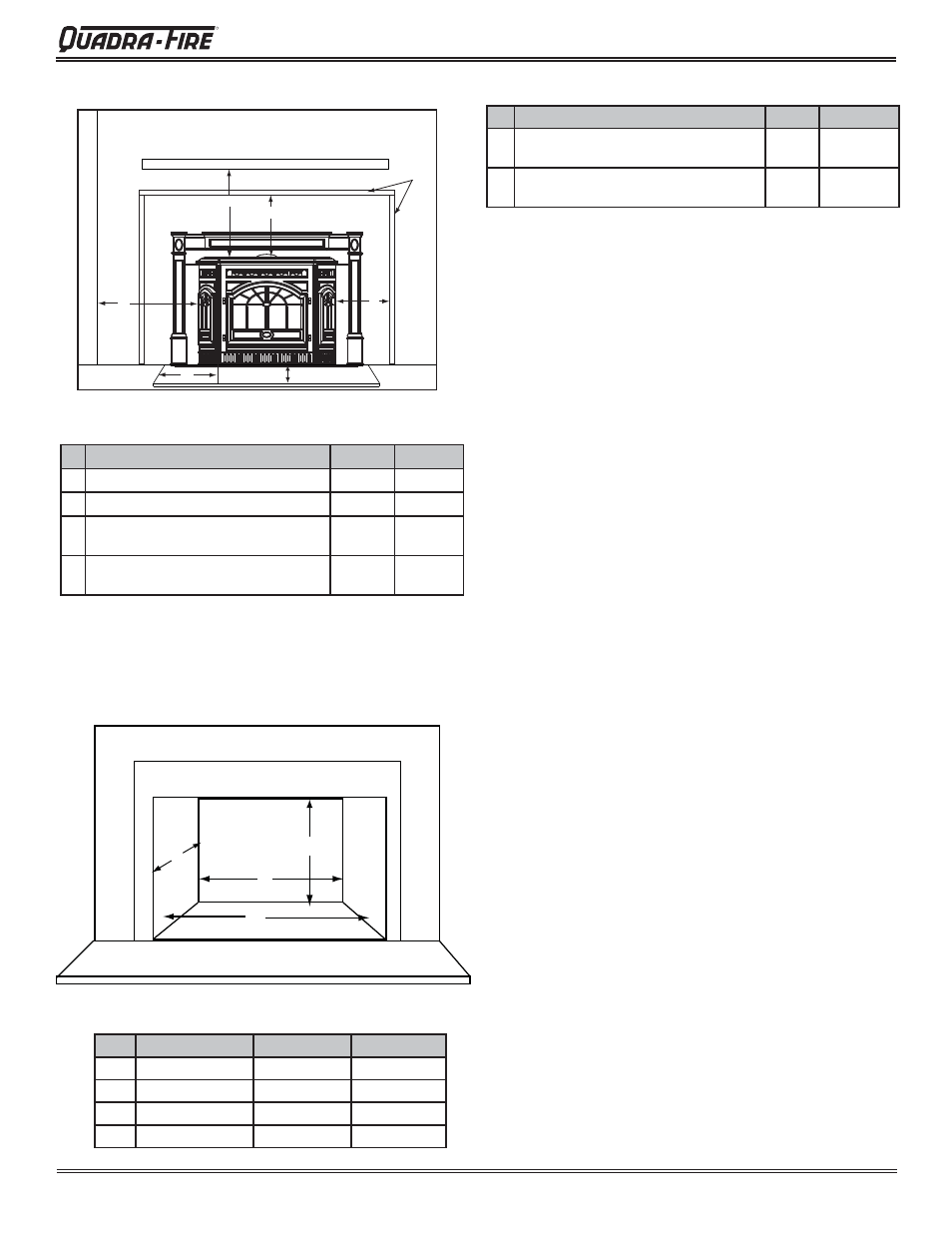
A
B
C
D
D. Minimum Opening for Masonry and
Factory-Built Fireplaces
Inches
Millimeters
A
Insert side to combustible side wall
16
406
B
Insert top to mantel
12
305
C
Insert top to maximum. 2-1/4 inch
(57mm) face trim
4-3/4
121
D
Insert side to maximum. 2-1/4 inch
(57mm) face trim
10
254
Location
Inches
Millimeters
A
Rear Width
23-5/8
600
B
Depth
17
432
C
Height
21-1/4
540
D
Front Width
28-1/8
714
Figure 11.1
C. Masonry and Factory-Built Fireplaces
Inches
Millimeters
E Floor protection hearth extension from
door opening
6
152
F
Floor protection to the side of door
opening
6
152
E. Floor Protection
Figure 11.2
Side W
all
Mantel
Maximum Mantel Depth: 12 inches (305mm)
Face
Trim
E
F
A
D
C
B
F. Prefabricated Metal Chimney
The chimney can be new or existing, masonry or prefabricated
and must meet the following minimum requirements:
• Must be minimum 6 inch (152mm) inside diameter of
high temperature chimney listed to UL 103 HT (2100
o
F)
or ULC-S628.
• Must use components required by the manufacturer for
installation.
• Must maintain clearances required by the manufacturer
for installation.
• Refer to manufacturers instructions for installation
•This insert is listed to UL 1482 Standard and is approved
for installation into listed factory-built zero clearance fi re-
places listed to UL 127 conforming to the following speci-
fi cations and instructions:
•The original factory-built zero clearance fi replace chim-
ney cap must be re-installed after installing the approved
chimney liner meeting type UL 103 HT requirements
(2100°F) per UL 1777.
•If the chimney is not listed as meeting HT requirements,
or if the factory built fi replace was tested prior to 1998, a
full height listed chimney liner must be installed from the
appliance fl ue collar to the chimney top.
•The liner must be securely attached to the insert fl ue collar
and the chimney top.
•The air fl ow of the factory-built zero-clearance fi replace
system must not be altered. The fl ue liner top support
attachment must not reduce the air fl ow for the existing
air-cooled chimney system.
•No dilution air is allowed to enter the chimney.
1. Secure the fi replace damper in the open position. If
this cannot be accomplished, it will be necessary to
remove the damper.
2. Seal damper area of chimney around chimney
connector with a high temperature sealant or seal
insert against the face of the fi replace.
3. Both methods must be removable and replaceable
for cleaning and re-installation.