Features & setup, Gain controls & input jacks – QSC Audio ISA 500T User Manual
Page 8
FEATURES & SETUP-
GAIN CONTROLS & INPUT JACKS
GAIN CONTROLS-
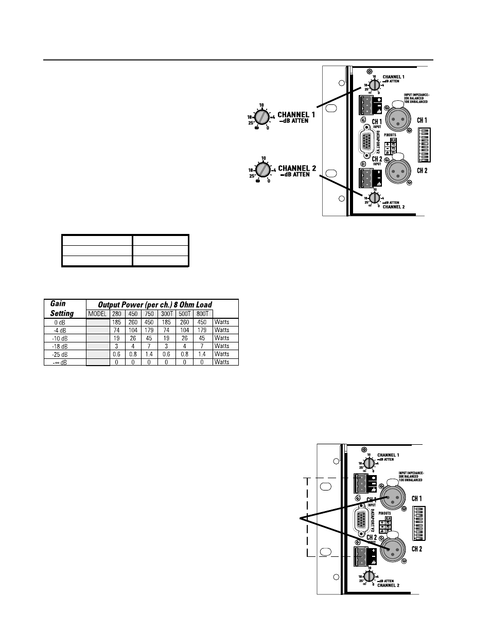
The Gain controls are located on the rear panel to minimize
control tampering after installation. When viewing the amplifier
from the rear, they are on the left end, top and bottom, as shown
in the illustration to the right.
The Gain controls are detented (11 steps) for repeatable
adjustment. Surrounding the Gain control, the power attenua-
tion level is shown in dB. To operate the Gain control, rotate the
control’s knob so that the desired level is achieved. There is a
detent in the knob to indicate its position.
Maximum gain depends on the model, see chart, below.
MAXIMUM VOLTAGE GAIN BY MODEL
ISA 280, 300T
30.5 dB
ISA 450, 500T
33.0 dB
ISA 750, 800T
35.0 dB
The attenuation level markings around the Gain controls are
power levels, not voltage. To have an idea of the approximate
output power, the table (at left) provides the output power by
model as a function of the Gain setting. The data provided is per
channel power for an 8 ohm load, input fully driven.
INPUTS-
The ISA series of amplifiers are equipped with XLR and terminal
block connectors. Input impedance is 20k ohm balanced, 10k
ohm unbalanced. The proper termination and connection
information is provided in the CONNECTIONS section of this
manual. Unused input connections may be used to daisy chain
the input to additional amplifiers.
Additionally, a DataPort V2 connector is provided for users of
QSC DataPort products. The DataPort V2 can be used to provide
input signals to the amplifier and to monitor the amplifier with
the appropriate QSC DataPort product. See the following section
for DataPort V2 information.
TERMINAL BLOCK
CONNECTORS
XLR CONNECTORS
8
WHERE THEY ARE-
WHERE THEY ARE-