Introduction, Rear panel illustrations – QSC Audio ISA 500T User Manual
Page 5
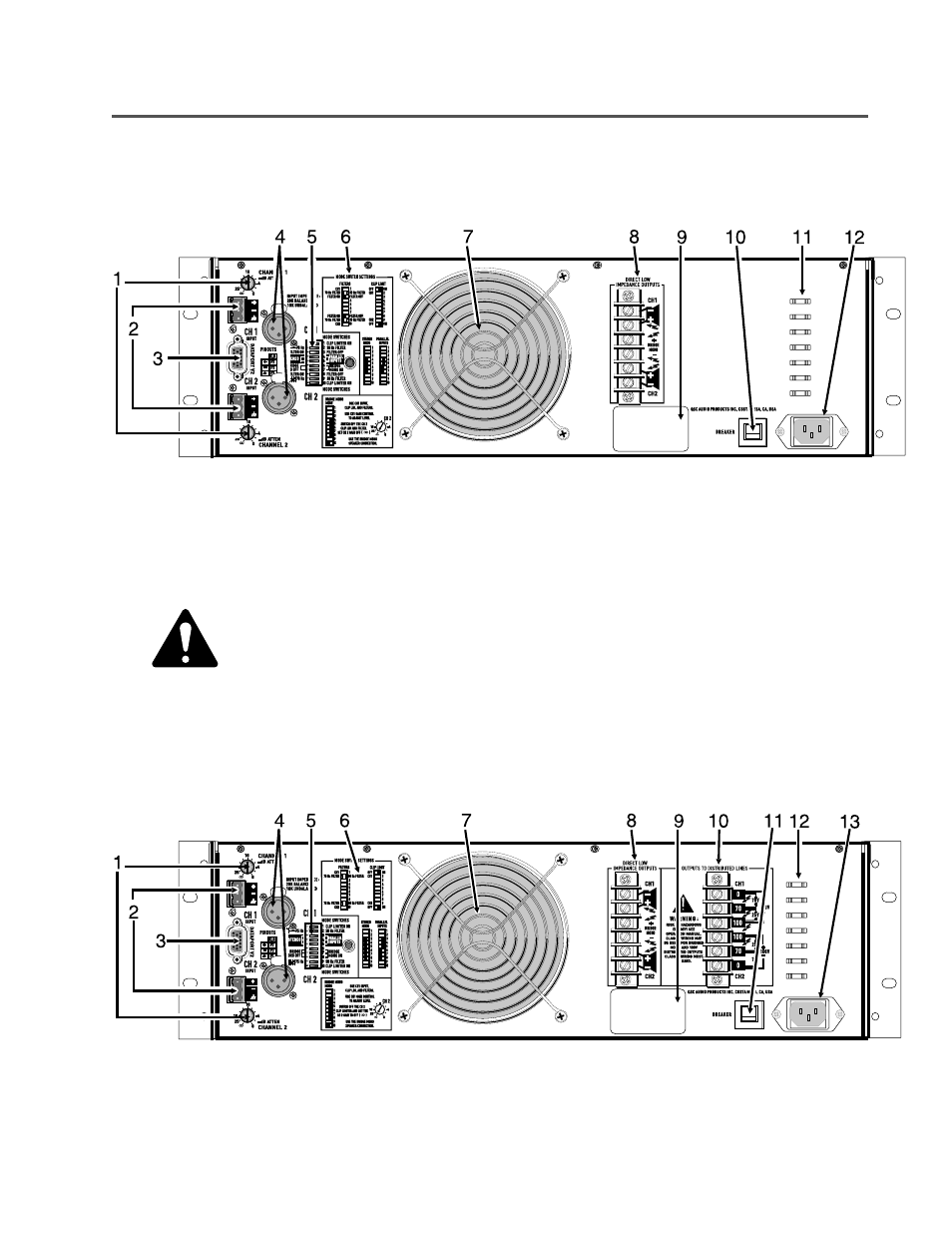
1. Gain Controls
2. Terminal Block Inputs
3. DataPort V2 Connector
4. XLR Inputs
INTRODUCTION-
REAR PANEL ILLUSTRATIONS
9. Serial Number Label
10. Circuit Breaker for AC Power
11. Tabs for Securing Output Wires
12. AC Power Connector, IEC type
REAR PANEL
ISA 280
ISA 450
ISA 750
5. Mode Switches
6. Mode Switch Configuration Charts
7. Cooling Air Inlet Vent
8. Output Connections, Low Impedance
REAR PANEL
ISA 300T
ISA 500T
ISA 800T
1. Gain Controls
2. Terminal Block Inputs
3. DataPort V2 Connector
4. XLR Inputs
5. Mode Switches
6. Mode Switch Configuration Charts
7. Cooling Air Inlet Vent
8. Output Connections, Low Impedance
9. Serial Number Label
10. Output Connections, Distributed (high impedance)
11. Circuit Breaker for AC Power
12. Tabs for Securing Output Wires
13. AC Power Connector, IEC type
5
NOTE! Output connection terminals shown without protective cover in place for clarity (rear panel, above & below).