English – Orbit Manufacturing Fluid 57926 User Manual
Page 14
1
ENGLISH
2. Mount the Docking Port
• Slide the timer off the docking port. (See Figure )
• Using the mounting template (included), mark the two
screw locations on the wall, then drill holes at the marks
for No. 8 screws. Use the expanding anchors in plaster or
masonry if necessary.
• Place the docking port against the wall, aligning the two
holes in the docking port with the two drilled holes.
• Secure the docking port to the wall by screwing a No. 8
screw (included) through each of the two holes.
• Do not slide the timer back onto the docking port yet.
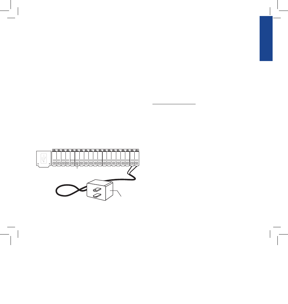
3. Connect the Transformer
• Find the two sockets at the bottom of the docking port
labeled “4VAC.” (See Figure 4)
• Insuring the transformer is not plugged in; insert one of
the two power leads from the transformer into each
terminal socket using the phillips screwdriver to depress
the terminal button (this allows for wire insertion or
removal).
• Plug in the transformer.
WARNING: Do not link two or more sprinkler timers together with
one transformer.
4. Connect Valve Wires to Timer, Pump Start and Master
Valve Sockets
A. Wire the Electric Valves
NOTE: If the distance between the sprinkler timer and valves
is under 700’ (210 m), use Orbit
®
sprinkler wire or 20 gauge
(AWG) plastic jacketed thermostat wire to connect the sprinkler
timer to the valves. If the distance is over 700’ (210 m), use 16
gauge (AWG) wire.
• Taking the sprinkler wire, strip 1/" (1 mm) of the
plastic insulation off the end of each individual wire.
• Connect one wire from each valve (it doesn’t matter
which wire) to a single “common” sprinkler wire. This
is usually white. (See Figure 5)
IMPORTANT: All wires should be joined together using wire
nuts, solder and/or vinyl tape. For additional protection to
waterproof connections, an Orbit
®
grease cap can be used.
• Next, connect the remaining wire from each valve to a
separate colored sprinkler wire.
Transformer
SENSOR
COM
PUMP
Terminal Button
1
2
3
4
5
6
7
8
9
10
11
12
24 VAC
Figure 4: Connecting the Transformer
07WTM002598 57926-24 rA.indd 13
2/16/07 2:07:24 PM