Oki MSM80C154S User Manual
Page 35
293
MSM80C154S/83C154S
¡ Semiconductor
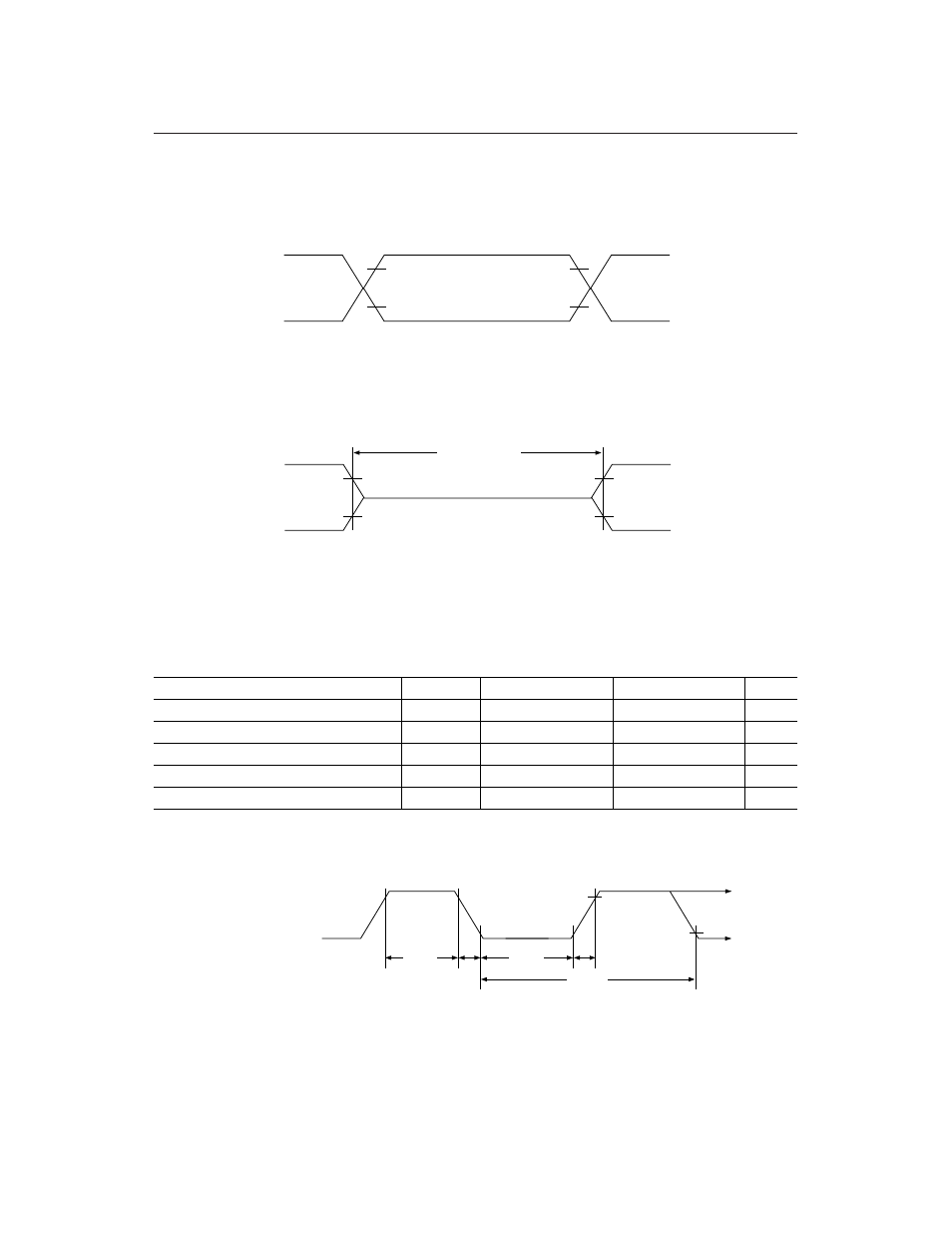
(7) AC Characteristics Measuring Conditions
1.Input/output signal
V
OH
V
OL
V
OH
V
OL
V
IH
V
IL
V
IH
V
IL
TEST POINT
*
The input signals in AC test mode are either V
OH
(logic "1") or V
OL
(logic "0") input signals
where logic "1" corresponds to a CPU output signal waveform measuring point in excess of
V
IH
, and logic "0" to a point below V
IL
.
2.Floating
V
OH
V
OL
V
OH
V
OL
V
IH
V
IL
V
IH
V
IL
Floating
*
The port 0 floating interval is measured from the time the port 0 pin voltage drops below V
IH
after sinking to GND at 2.4 mA when switching to floating status from a "1" output, and from
the time the port 0 pin voltage exceeds V
IL
after connecting to a 400
mA source when switching
to floating status from a "0" output.
(8) XTAL1 external clock input waveform conditions
Parameter
Symbol
Min.
Max.
Unit
External Clock Freq.
1/t
CLCL
0
24
MHz
Clock Pulse width 1
t
CHCx
15
—
Clock Pulse width 2
t
CLCX
15
—
Rise Time
t
CLCH
—
5
Fall Time
t
CHCL
—
5
ns
ns
ns
ns
External Clock Drive Waveform
0.7 V
CC
0.2 V
CC
- 0.1
t
CHCL
t
CLCH
t
CLCX
t
CLCL
t
CHCX
EXTERNAL
OSCILLATOR
SIGNAL