2) install module in chassis and connect cables, 3) configure module via command line interface, Dip-switch bank 2 – Omnitron Systems Technology Omnitron iConverter GX/TM2 User Manual
Page 2
SW3 - MASTER/SLAVE
When the GX/TM2 module is installed in a chassis with an
iConverter
management
module such as a 10/100M2, set the DIP-switch to the LEFT “M/SL” position (factory
default), the assignment of mastership is automatically negotiated by the installed
management modules. To designate the GX/TM2 module as the master of the chassis,
set the DIP-switch on the module to
the LEFT “M/SL” position, and set the
DIP-switch on the other installed
management modules to the RIGHT
“SL” position to enable Slave-Only
mode.
SW4 - RESERVED
This DIP-switch is for factory use only and must always remain in the LEFT position
(factory default).
2) INSTALL MODULE IN CHASSIS AND CONNECT CABLES
a. Carefully slide the module into an open slot in the chassis. Align the module with
the installation guides and ensure that the module is firmly seated against the
backplane. Secure the module by fastening the front panel thumbscrew (push in
and turn clockwise to tighten) to the chassis front. Verify the “Pwr” LED is ON
(indicating the chassis is powered).
b. When using a GX/TM2 SFP model (8939N-0), insert the SFP Fiber transceiver into
the Port 1 SFP receptacle on the GX/TM2.
NOTE: The release latch of the SFP Fiber transceiver must be in the closed
position before insertion.
c. Connect the UTP port via a Category 5 cable to a 10BASE-T, 100BASE-TX or
1000BASE-T Ethernet device.
d. Connect an appropriate multimode or single-mode fiber cable to the fiber port of
the installed module. It is important to ensure that the transmit (Tx) is attached to
the receive side of the device at the other end and the receive (Rx) is attached to
the transmit side. Single-fiber (SF) media converter models operate in pairs. The
Tx wavelength must match the Rx wavelength at the other end and the Rx wavelength
must match the Tx wavelength at the other end
3) CONFIGURE MODULE VIA COMMAND LINE INTERFACE
To access the Command Line Interface (CLI), connect the GX/TM2 RS-232 Console
Port to the COM port of a computer equipped with terminal emulation software such as
HyperTerminal. The Console Port (DCE) is a mini DIN-6 female connector which can
be changed to a DB-9 connector with the included adapter. The GX/TM2 Console Port
is a standard asynchronous serial interface.
Start HyperTerminal and select the correct COM Port in the HyperTerminal “Connect
To:” window. Set the serial port to the following:
Bits Per Second
57,600
Stop Bits
1
Data Bits
8
Parity
NONE
Hardware Flow Control
NONE
Once connected, press <ENTER> to bring up a command line prompt on the attached
PC.
SW3 - UTP SPEED GIGABIT/10-100 “1000/10-100”
When the “1000/10-100” DIP-switch is in the “1000” position (factory default), the
UTP port operates in 10/100/1000Mbps Auto-Negotiation mode. The UTP port
auto-negotiates to a speed of 10Mbps, 100Mbps or 1000Mbps with the connected
UTP device. In this mode, the UTP “AN/Man” and UTP “100/10” DIP-switches have no
effect.
When the “1000/10-100” DIP-switch is in the “10-100” position and the UTP “AN/Man”
DIP-switch is in the “Man” position, the UTP port operates at the Speed and Duplex
modes set by the “100/10” and “FDX/HDX” DIP-switches.
When the “1000/10-100” DIP-switch is in the “10-100” position and the UTP “AN/Man”
DIP-switch is in the “AN” position, the UTP port maximum auto-negotiation setting
for the Speed and Duplex mode is determined by the “100/10” and “FDX/HDX”
DIP-switches.
SW4 - UTP 100/10MBPS “100/10”
When the UTP “AN/Man” DIP-switch (described above) is in the manual “Man” position,
the “100/10" DIP-switch determines the speed of operation for the UTP port. Set the
“100/10” DIP-switch to match the speed of the connected UTP device.
SW5 - UTP FULL/HALF DUPLEX “FDX/HDX”
When the UTP “AN/Man” DIP-switch (described above) is in the manual “Man” position,
the “FDX/HDX" DIP-switch determines the duplex mode of the UTP port. Set the
“FDX/HDX” DIP-switch to match the duplex mode of the connected UTP device.
SW6, SW7, SW8 - LINK MODES
These three DIP-switches configure the link mode settings. The following table details
possible Link Mode DIP-switch configurations.
Switch
Left
(Factory Default)
Right
SW6
SW7
SW8
Link Mode Selection
SW1 AN:
Fiber Auto-Negotiation
Man:
Fiber Manual Negotiation
Left
Left
Left
Link Segment (LS)
(Factory Default)
SW2 AN:
UTP Auto-Negotiation
Man:
UTP Manual
Right
Left
Left
Link Propagate (LP)
SW3 1000:
UTP 1000Mbps
10-100:
UTP 10-100Mbps
Left
Right
Left
Remote Fault Detect + Link
Segment (RFD + LS)
SW4 100:
UTP 100Mbps
10:
UTP 10Mbps
Right
Right
Left
Remote Fault Detect + Link
Propagate (RFD + LP)
SW5 FDX:
UTP Full-Duplex
HDX:
UTP Half-Duplex
Left
Left
Right Symmetrical Fault Detect (SFD)
SW6
See Link Mode Selection
Right
Left
Right Asymmetrical Link Propagate
Port 1 to Port 2 (ALP P1-P2)
SW7
Left
Right
Right Asymmetrical Link Propagate
Port 2 to Port 1 (ALP P2-P1)
SW8
Right
Right
Right Asymmetrical RFD+LP
Port 1 to Port 2 (ARFDP1-P2)
Figure B: DIP-Switch Bank 1
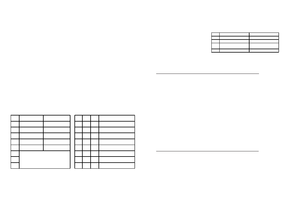
DIP-SWITCH BANK 2
SW1, SW2 - BACKPLANE ENABLE
When the DIP-switch is in the LEFT “DS” position (factory default), the Backplane Port
of the GX/TM2 is isolated from the chassis’ Ethernet Backplane. When this DIP-switch
is in the RIGHT “EN” position, the Backplane Port is enabled. This allows Ethernet
Backplane connectivity to an adjacent module via the chassis Backplane Link “A” or
“B” depending on the switch setting.
Switch
Left (Factory Default)
Right
SW1 A-DS: Port A Disabled
A-EN: Port A Enabled
SW2 B-DS: Port B Disabled
B-EN: Port B Enabled
SW3 M/SL:
Master/Slave Auto-Select
SL:
Slave-Mode Only
SW4 Reserved
Reserved
Figure C: DIP-Switch Bank 2