Readjusting input / output, Signal output jumpers – Omega Vehicle Security DRF-RES Series User Manual
Page 8
Page 8
User’s Manual Series DRF
6-READJUSTING INPUT / OUTPUT
To change the input/output relation of the
instrument, proceed as indicated below :
(Following values in brackets are examples for
readjusting the input/output relation of the instrument
to 0/100% = 0/10 Vdc and input type potentiometer)
1.- Open the front cover
2.- Select the required input jumpers
(Section
4, page 6)
3.- Select the required output jumpers
(Section
5, page 7)
4.- Connect a potentiometer to the input
terminals
(Section 3, page 5)
5.- Connect a multimeter to the output terminals
(4 and 5 for mA or 4 and 6 for Vdc)
6.- Generate the low input signal
(0%)
Operate the OFFSET potentiometer, until
the low output value is reached
(0Vdc)
7.-
Generate the high input signal
(100%)
Operate the SPAN potentiometer, until the
high output value is reached
(10Vdc)
8.- Repeat 6 and 7 to improve the accuracy
until it reaches its specified value
9.- Close the front cover
IMPORTANT - Opening the
front cover may grant access
to areas with dangerous
voltages. Operations must be
performed by qualified
technical staff.
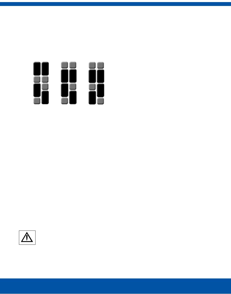
5-SIGNAL OUTPUT JUMPERS___
The position of the output jumpers selects
the range for the output signal as indicated
below.
0/1 V
DC
0/10 V
DC
4/20 mA
0/20 mA
J1
J2
J3
J4
J5
J6