Orion SKYQUEST XT10 User Manual
Page 7
7
SkyQuest Intelliscope Dobsonians employ a simple yet effec-
tive remedy for the friction problem that obviates the need for
such cumbersome countermeasures. CorrecTension Friction
Optimization utilizes a simple “disc brake” to apply the correct
level of tension to the altitude bearings. With the XT system,
you can change eyepieces or add a barlow lens without hav-
ing to tediously adjust the telescope’s balance as you would
with other Dobsonians. The altitude friction can be made
equal to the azimuth friction, ensuring optimal performance.
To install the XT system, follow these steps while referring to
Figures 10 and 11:
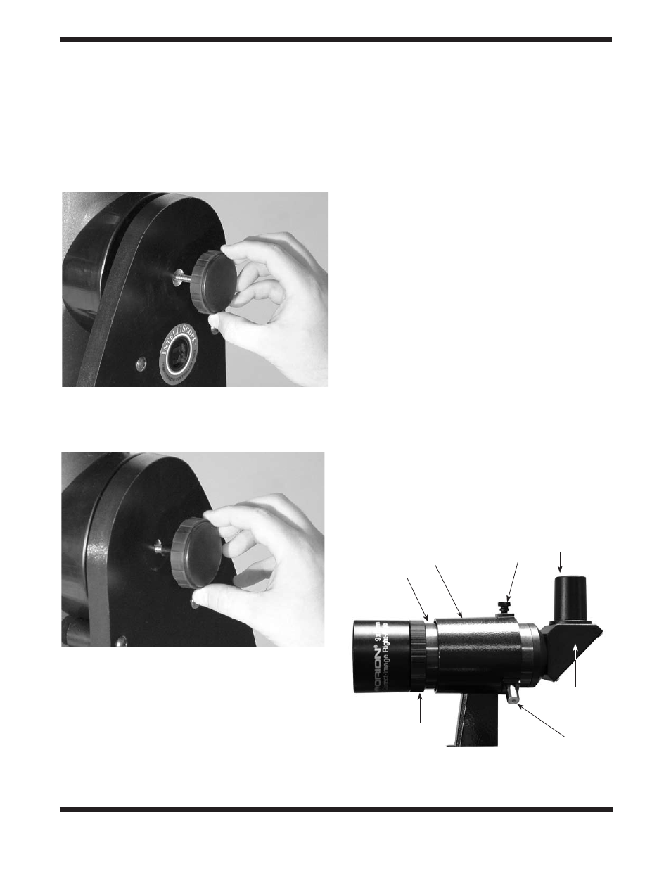
1. Select one of the retaining/tensioning knobs and slide the
metal washer onto the shaft, followed by the white nylon
washer (you will need to thread this washer onto the shaft).
This knob will now be known as the tensioning knob. Push the
shaft of the tensioning knob through the hole in the side
panel that has the IntellisScope port (Figure 10). Thread
the knob into the altitude bearing until the CorrecTension
pads on the interior surface of the side panel just touch the
side of the altitude bearing on the optical tube.
2. Place the black nylon retaining knob spacer on the shaft of
the remaining retaining/tensioning knob. This knob will
now be known as the retaining knob. Push the shaft of the
retaining knob through the hole in the side panel opposite
the one the retaining knob is in (Figure 11). Thread the
knob into the altitude bearing as far as it will go. The purpose
of this knob is to allow the tube and base to be carried as a
single unit as well as to engage the altitude encoder
when using the IntelliScope controller. There will be a gap of
1/2" between the side panel and the side bearing; this was
designed deliberately for use of the IntelliScope controller
system.
Note: Only the left side panel has a white nylon bushing
in the hole for the tensioning knob. The right side panel
does not require this bushing.
The CorrecTension system is now installed. If you wish to
remove the optical tube from the base, you will first need to
unthread and remove both the knobs (and spacers/washers).
Once the optical tube is removed from the base, thread the
knobs back into the altitude bearings so you do not lose
them.
installing the Finder Scope
SkyQuest IntelliScope Dobsonians come with a high-quality,
large-aperture 9x50 (6x30 for the XT6) right-angle correct-
image achromatic crosshair finder scope (Figure 12) as
standard equipment. This greatly aids in finding objects to
view in the night sky.
The finder scope arrives pre-installed in its bracket, but must
be placed into the dovetail holder on the telescope tube. Insert
the base of the finder scope into the dovetail holder located
adjacent to the focuser (Figure 12b). Lock the bracket into
position by tightening the knurled thumbscrew on the dovetail
holder.
Figure 11.
The retaining knob with the nylon spacer is installed
on the side of the base that does not have the IntelliScope port.
Figure 10.
The tensioning knob, with the metal and nylon
washers, goes on the side of the base with the IntelliScope port. The
tensioning knob should be tightened until the CorrecTension pads
just touch the telescope’s altitude bearing.
Figure 12a.
The 9x50 right-angle correct-image finder scope
and bracket (6x30 for the XT6).
Tensioner
Eyepiece
Nylon alignment
thumbscrew (2)
Focusing lock ring
Finder scope
Finder scope bracket
Correct-Image
prism housing