Orion XT6 User Manual
Page 5
5
the baseplate. Thread an encoder board mounting screw
into the predrilled starter hole with a Phillips screwdriver
and tighten until just tight.
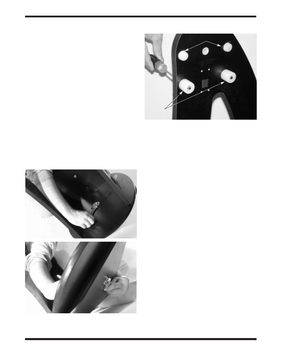
6. Place one Teflon bearing pad (G) into each recessed hole
on the ground baseplate (A). The bearing pads will be loose
in the recessed hole and should remain that way. Do not
attempt to permanently secure the bearing pads by any
means as this will interfere with the motion of the telescope.
7. Place one fender washer (H) onto the azimuth axis screw
(I). Then push the screw up through the hole in the ground
baseplate (A).Then slide the encoder disk (J), flat side
down, onto the azimuth axis screw.
8. Place the brass bushing (F) onto the azimuth axis screw (I)
so that the wide end of the bushing is closest to the
encoder disk (J). Seat the bushing onto the encoder disk
so that the registration feature on the bushing goes into
the hole in the encoder disk. You may need to move the
encoder disk around on the azimuth axis screw a bit in
order for the bushing to seat properly.
9. Carefully position the top baseplate (D) over the ground
baseplate (A) and lower it so the brass bushing (F) goes
into in the center hole of the top baseplate. Place the
remaining fender washer (K) onto the shaft of the azimuth
axis screw, then thread the hex lock nut (L) onto the end
of the azimuth axis screw and tighten it finger tight, for
now.
10. To tighten the azimuth axis screw (I) and hex lock nut (L),
tilt the assembled Dobsonian base at a slight angle to lift
the ground baseplate off the ground. Do not turn the base
on its side, as this will cause the Teflon bearing pads to fall
out. Now, with one wrench (or pliers) hold the head of the
azimuth axis screw still while turning the hex lock nut with
the other wrench. Figure 4 shows this being done. Tighten
the hex lock nut just until the top fender washer is no
longer moving freely, then tighten the hex nut a 3/16-1/4
turn beyond that. This ensures proper spacing between
the encoder disk and the azimuth encoder board.
11. Attach the handle (M) to the front brace (B) with the two
handle mounting hex-head screws. Place one washer on
each screw, then press the handle against the front brace
(the end of the handle with the logo should be up). Then
thread the screws from the inside of the base into the han-
dle until tight using the supplied crescent wrench.
12. Line up one of the altitude bearing cylinders with the
inside of one of the four bearing cylinder holes on the side
panels. Push a bearing cylinder screw through the side
panel and bearing cylinder. Then thread it into the built-in
hex nut on the cylinder with a Phillips head screwdriver
(Figure 5). The beveled end of the cylinder should be fac-
ing away from the side panel. Repeat this for the
remaining three bearing cylinders.
13. Attach the encoder connector board to the side panel. Place
the board against the side panel so that the modular jack fits
into the square-shaped hole and thread four encoder board
mounting screws through the connector board and into the
predrilled holes in the side panel until tight (Figure 6).
There are some predrilled holes on the side panel opposite
the panel that holds the encoder connector board. These
holes will be used to mount parts that come with the optional
IntelliScope controller. If you purchased the IntelliScope con-
troller with your SkyQuest, you will want to follow the
installation instructions in the controller’s manual at this time.
Installing the Vertical Stop
Place the nylon spacer (white) and the three flat washers
onto the shaft of the vertical stop screw. Thread the vertical
stop into the threaded hole on the inside of front panel until
tight (Figure 7). The position of the vertical stop is adjustable
Figure 4.
To connect the baseplates, tilt them only slightly, as shown.
Do not place them on their side.
(a)
Use one wrench to hold the hex
nut steady
(b)
while turning the other end of the azimuth axis screw.
Figure 5.
Attaching the bearing cylinders. (XT10 Shown)
b.
a.
Correct Tension pads
Bearing
cylinders