4 combustion fan vertical installation – Roberts Gorden UHA SERIES 200 User Manual
Page 40
COMBAT
®
UHA U
NIT
H
EATER
I
NSTALLATION
O
PERATION
AND
S
ERVICE
M
ANUAL
34
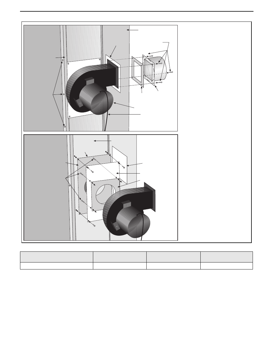
14.4 Combustion Fan Vertical Installation
Vent Box
Outlet
Gasket
Flue Fan
Vent Box
Screws
Flue
Adapter
Flue Adapter
to Flue Fan
screws
Rear Panel
Hole
Disconnect
electrical connections
at plug in tabs.
Mounting Plate
to Vent Box
Screws
Mounting
Plate
Gasket
Air Plate
Mounting Plate
to Flue Fan
Screws
Vent Box
Gasket
Remove screws securing outlet
flange to the flue adapter.
Refit in reverse order.
Remove screws securing flue
fan mounting plate to vent box.
Remove screws securing
mounting plate to fan.
Refit in reverse.
Use new gaskets.
Ensure sealed joints.
Ensure mounting plate orifice is
clear and not obstructed.
MODEL
UHA[S]
150 - 175
UHA[S]
200 - 300
UHA[S]
350 - 400
Exhaust Fan P/N
90710405
90710403
90710402
IT IS IMPORTANT THAT ONLY THE CORRECT COMBUSTION FAN SPECIFIED FOR EACH MODEL
TYPE IS USED WHEN REPLACING THESE ITEMS.
Carry out a start-up after working on or changing a combustion fan. See Page 22, Section 11.