Attach the power and relay connector – Rockwell Tools STRATIX 8000 ETHERNET 1783-MS10T User Manual
Page 42
42
Publication 1783-UM002C-EN-P - April 2009
Chapter 2
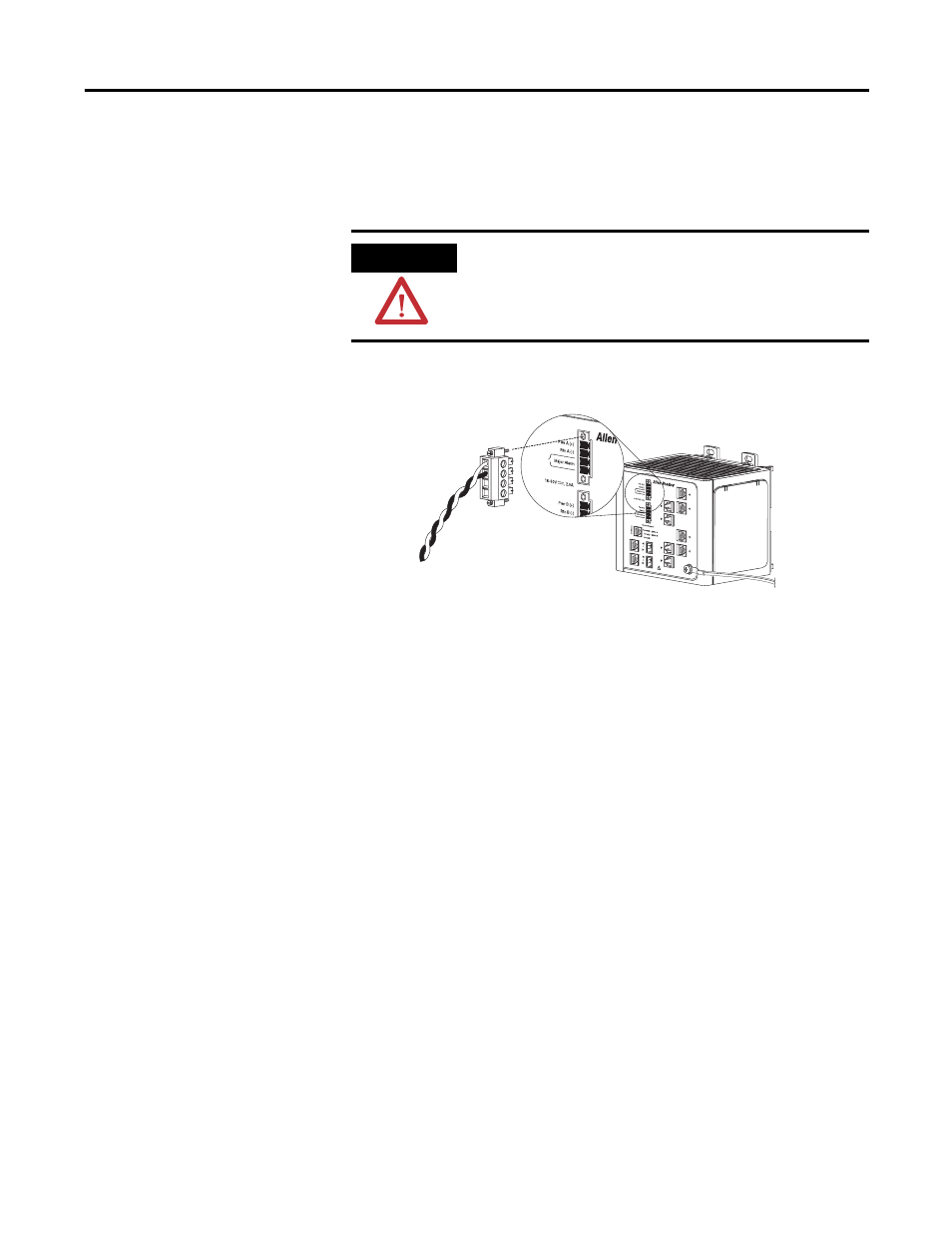
Attach the Power and Relay Connector
Follow these steps to connect the DC power and relay connector to the switch:.
1.
Insert the power and relay connector into the Pwr A receptacle on the
switch front panel.
2.
Use a screwdriver to tighten the captive screws on the sides of the power
and relay connector.
ATTENTION
The input voltage source of the alarm circuits must be an
isolated source and limited to less than or equal to 30V DC, 1 A.
VR
T
A
A
31786-M
This manual is related to the following products: