2" (5 cm) – Roberts Gorden Vantage TF TF-160 User Manual
Page 26
TF-S
ERIES
I
NSTALLATION
, O
PERATION
AND
S
ERVICE
M
ANUAL
20
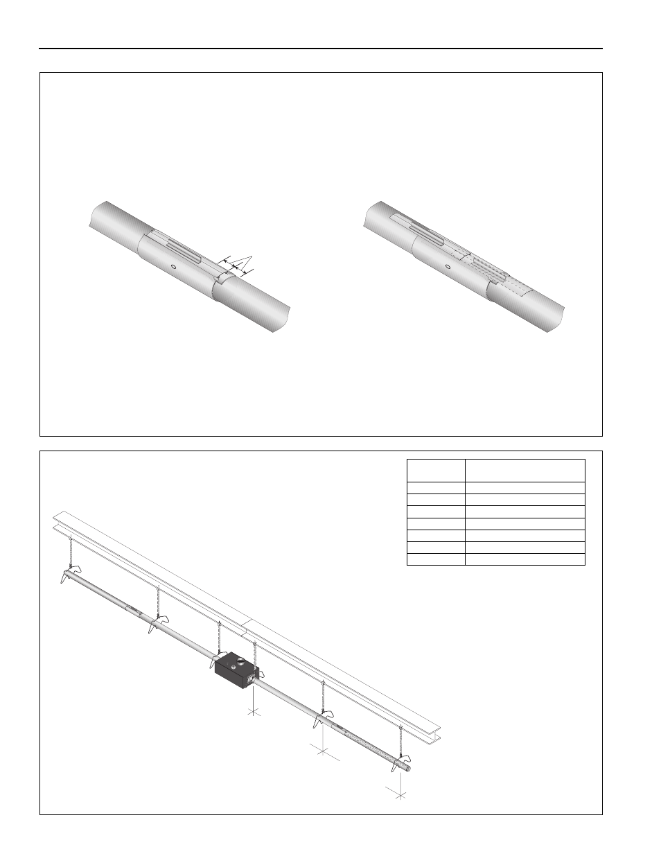
Step 7.4.1 Coupling and Tube Assembly (Continued)
Step 7.4.2 Coupling and Tube Assembly (Continued)
Incorrect Slide Bar
position
Correct Slide Bar
dimensions
± 2" (5 cm)
Drive Slide Bar until tight.
End of Slide Bar should be
within tolerance listed below.
• Repeat Step 7.4 A - D until all tubes are assembled. See Page 20, Section 7.4.2.
Tighten slide bar as shown below
10' Typ. ± 1'
(254 cm Typ ± 25 cm)
7' 6" ± 1'
(229 cm ± 25 cm)
Model
Minimum Tube Length
Per Side
TF-120
20’ (6 m)
TF-160
20’ (6 m)
TF-200
30’ (9 m)
TF-250
40’ (12 m)
TF-300
50’ (15 m)
TF-350
50’ (15 m)
TF-380
60’ (18 m)
See recommended venting lengths
on Page 34, Section 9, when using
maximum tube lengths.
This manual is related to the following products: