Roberts Gorden VANTAGE HE HE-125 User Manual
Page 14
HE-S
ERIES
I
NSTALLATION
, O
PERATION
AND
S
ERVICE
M
ANUAL
8
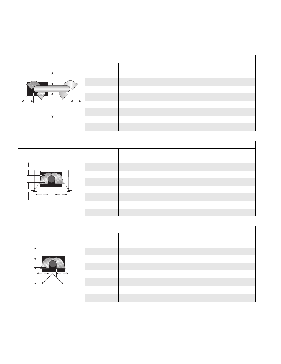
NOTE: 1. All dimensions are from the surfaces of all tubes, couplings and elbows.
2. Clearances B, C and D can be reduced by 50% after 25' (7.5 m) of tubing downstream
from where the burner and burner tube connect.
*When installed in the first 10' (3 m).
FIGURE 9: U-TUBE, OPPOSITE 45
°
REFLECTOR
(inches)
(centimeters)
Model
A
B
C
D
A
B
C
D
HE-40
- UNAPPROVED -
- UNAPPROVED -
HE-60
8
54
60
22
21
138
153
56
HE-80
8
60
66
22
21
153
168
56
HE-100
10
64
74
22
26
163
188
56
HE-125
10
70
78
22
26
178
199
56
HE-150
12
74
84
22
31
188
214
56
HE-175
12
76
85
22
31
194
216
56
A
C
D
B
FIGURE 10: 2-FOOT DECO GRILLE AND PROTECTIVE GRILLE
(inches)
(centimeters)
Model
A
B
C
D
A
B
C
D
HE-40
6
27
53
27
16
69
135
69
HE-60
6
35
63
35
16
89
161
89
HE-80
6
38
66
38
16
97
168
97
HE-100
6
40
71
40
16
102
181
102
HE-125
6
46
77
46
16
117
196
117
HE-150
6
50
80
50
16
127
204
127
HE-175
8
52
82
52
21
133
209
133
A
C
D
B
FIGURE 11: LOWER CLEARANCE SHIELD*
(inches)
(centimeters)
Model
A
B
C
D
A
B
C
D
HE-40
6
34
27
34
16
87
69
87
HE-60
6
39
33
39
16
100
84
100
HE-80
6
40
38
40
16
102
97
102
HE-100
6
50
44
50
16
127
112
127
HE-125
6
54
48
54
16
138
122
138
HE-150
6
55
50
55
16
140
127
140
HE-175
- UNAPPROVED -
- UNAPPROVED -
A
C
D
B