Roberts Gorden VANTAGE HE HE-125 User Manual
Page 13
SECTION 3: C
LEARANCES
TO
C
OMBUSTIBLES
7
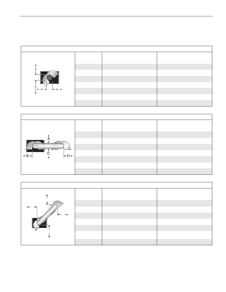
NOTE: 1. All dimensions are from the surfaces of all tubes, couplings and elbows.
2. Clearances B, C and D can be reduced by 50% after 25' (7.5 m) of tubing downstream
from where the burner and burner tube connect.
FIGURE 6: 45
°
TILT REFLECTOR
(inches)
(centimeters)
Model
A
B
C
D
A
B
C
D
HE-40
8
8
51
46
21
21
130
117
HE-60
8
8
60
54
21
21
153
138
HE-80
8
8
66
60
21
21
168
153
HE-100
10
8
74
64
26
21
188
163
HE-125
10
8
78
69
26
21
199
176
HE-150
12
8
84
74
31
21
214
188
HE-175
12
8
85
79
31
21
216
201
FIGURE 7: U-TUBE, STANDARD REFLECTOR
(inches)
(centimeters)
Model
A
B
C
D
A
B
C
D
HE-40
- UNAPPROVED -
- UNAPPROVED -
HE-60
6
35
63
30
16
89
161
77
HE-80
6
38
69
37
16
97
176
94
HE-100
6
40
76
39
16
102
194
100
HE-125
6
46
79
43
16
117
201
110
HE-150
6
50
84
47
16
127
214
120
HE-175
8
54
87
51
21
138
221
130
FIGURE 8: U-TUBE, 45
°
(inches)
(centimeters)
Model
A
B
C
D
A
B
C
D
HE-40
- UNAPPROVED -
- UNAPPROVED -
HE-60
8
8
60
42
21
21
153
107
HE-80
8
8
66
46
21
21
168
117
HE-100
8
8
74
52
21
21
188
133
HE-125
8
8
78
61
21
21
199
155
HE-150
8
8
84
66
21
21
214
168
HE-175
8
8
85
70
21
21
216
178
B
C
D
A