Roberts Gorden VANTAGE HE HE-125 User Manual
Page 12
HE-S
ERIES
I
NSTALLATION
, O
PERATION
AND
S
ERVICE
M
ANUAL
6
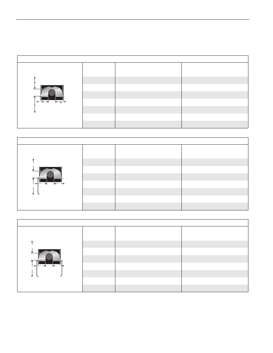
NOTE: 1. All dimensions are from the surfaces of all tubes, couplings and elbows.
2. Clearances B, C and D can be reduced by 50% after 25' (7.5 m) of tubing downstream
from where the burner and burner tube connect.
FIGURE 3: STANDARD REFLECTOR
(inches)
(centimeters)
Model
A
B
C
D
A
B
C
D
HE-40
6
27
53
27
16
69
135
69
HE-60
6
35
63
35
16
89
161
89
HE-80
6
38
66
38
16
97
168
97
HE-100
6
40
71
40
16
102
181
102
HE-125
6
46
77
46
16
117
196
117
HE-150
6
50
80
50
16
127
204
127
HE-175
8
52
82
52
21
133
209
133
FIGURE 4: ONE SIDE REFLECTOR
(inches)
(centimeters)
Model
A
B
C
D
A
B
C
D
HE-40
6
9
53
44
16
23
135
112
HE-60
6
9
63
47
16
23
161
120
HE-80
6
9
70
54
16
23
178
138
HE-100
6
9
77
59
16
23
196
150
HE-125
6
9
83
65
16
23
211
166
HE-150
6
9
86
69
16
23
219
176
HE-175
8
9
88
73
21
23
224
186
A
C
D
B
FIGURE 5: TWO SIDE REFLECTORS
(inches)
(centimeters)
Model
A
B
C
D
A
B
C
D
HE-40
6
15
53
15
16
39
135
39
HE-60
6
23
66
23
16
59
168
59
HE-80
6
25
72
25
16
64
183
64
HE-100
6
27
78
27
16
69
199
69
HE-125
6
32
84
32
16
82
214
82
HE-150
6
35
88
35
16
89
224
89
HE-175
8
40
91
40
21
102
232
102
A
C
D
B