Assembly – RIDGID TS2400 User Manual
Page 10
10
ASSEMBLY
n
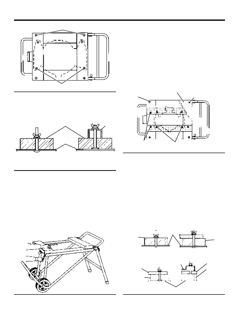
Remove mounting blocks from table. Attach power tool
to mounting blocks with 1/4-20 carriage bolts, washers,
lockwashers and nuts as shown. Reinstall mounting
blocks to work stand table.
NOTE: See views of bolt recommendations, see figure 15.
Fig. 14
Portable Power Tools with a Small Base
See Figures 16, 17 and 18.
(Tool mounting holes do not span 2 x 6 mounting blocks
shown.)
n
Place the stand in the set-up position as shown.
n
Using the stand’s table as a pattern, locate the 2 x 6 s as
shown, and from the bottom mark hole locations.
n
Drill 1/4 in. or 3/8 in. diameter holes in the two 2 x 6 x 24
in. long mounting blocks as shown.
n
Temporarily attach the mounting blocks to work stand
with the supplied bolts or 1/4-20 bolts at least 2-1/2 in.
long. Secure with washers, lockwashers and nuts.
n
Locate and drill holes in 2 x 6 mounting blocks and 1 x
4 cross pieces, as shown. Plywood 3/4 in. thick, 24 in. x
27 in. may be used in place of the 1 x 4 s.
n
Loosen 2 x 6 mounting blocks from work stand table.
Attach two 1 x 4 cross pieces to the mounting blocks
with 1/4-20 carriage bolts at least 2.75 inches long, as
shown. Secure with washers, lockwashers and nuts.
NOTE: A 5/8” diameter counterbore 1/4” deep is
required for clearance between the bolt head and the
Fig. 16
Fig. 17
work stand table. Tap carriage bolt with hammer to seat
bolt fully into the hole and counterbore. Resecure 2x6
mounting blocks to work stand table.
If using plywood, the supplied 1/4-20 bolts may be used to
attach the 2 x 6s and plywood to the work stand table.
When mounting table saws to plywood an opening for the
sawdust to fall through is needed. See your tools owner’s
manual for recommended hole size.
See views of bolt recommendations, see figure 18.
n
To attach power tool, locate and drill holes in cross
pieces.
n
Attach power tool to cross pieces with 1/4-20 carriage
bolts as shown with washers, lockwashers and nuts.
Fig. 18
SET-UP POSITION
SEE BOLT VIEW A
SEE BOLT VIEW B
Fig. 15
BOLT VIEW A
(2 X 6s WORK STAND)
BOLT VIEW B
(POWER TOOL TO 2 X 6s)
WORK
STAND
2 X 6
POWER
TOOL
SEE BOLT
VIEW A-1
SEE BOLT
VIEW A
SEE BOLT
VIEW C
SEE BOLT
VIEW B
PLYWOOD
WORK
STAND
WORK STAND
BOLT VIEW A
(2 X 6s TO WORK STAND)
BOLT VIEW A-1
(PLYWOOD AND 2 X 6s
TO WORK STAND)
BOLT VIEW B
(1 X 4s TO 2 X 6s)
BOLT VIEW C
(POWER TOOL TO
1X4s OR
2 X 6
2 X 6
2 X 6
1 X 4
2 X 6
1 X 4 OR
PLYWOOD
POWER
TOOL