Connecting an external ir receiver, Figure 3-8 . external ir receiver connection, Rs-232 controller connection – Runco CRYSTAL CX-OPAL47 User Manual
Page 35: Figure 3-9 . rs-232 control system connection, 8. external ir receiver connection, 9. rs-232 control system connection, Pre l iminar y
CX-47HD/CX-OPAL47/CX-65HD Installation/Operation Manual
21
PRE
L
IMINAR
Y
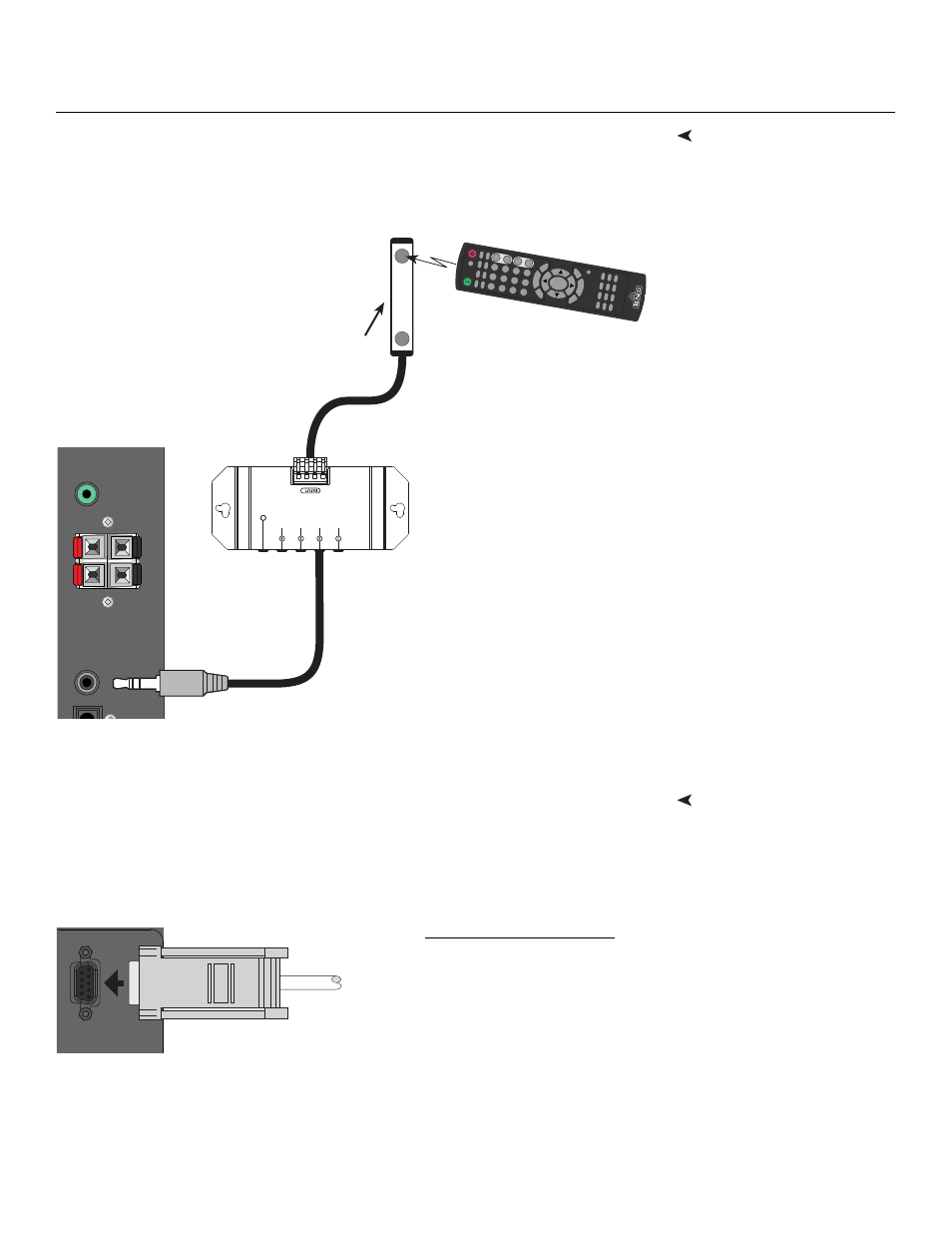
Connecting an External IR
Receiver
If infrared signals from the remote control cannot reach the display due to excessive
distance or obstructions such as walls or cabinet doors, you can connect an external IR
repeater system to the IR INPUT on the Crystal Series LCD to extend the range of the
remote control. See Figure 3-8.
Figure 3-8. External IR Receiver Connection
RS-232 Controller
Connection
Use a straight-through RS-232 cable with a 9-pin male connector to connect a PC or
home theater control/automation system (if present) to the RS-232 port on the Crystal
Series LCD; see Figure 3-9.
For more information about using this connection, refer to Serial Communications on
page 47.
Figure 3-9. RS-232 Control System Connection
PC
Audio In
Speaker Out
SPDI
IR
In
L
R
–
+
RGB
16:9
4:3
L
ETTER
V
WIDE
TIMER OFF
VO
L-
V
O
L+
E
N
T
E
R
M
EN
U
C
U
S
T
O
M
PIP
1
2
3
+
4
5
6
–
7
8
9
+
100
0
MUTE
–
POSITION
SIZE
SW
AP
HDMI 1
H
DMI 2
HDMI 3
H
DMI 4
COMP
1
COMP
2
V
ID 1
V
ID 2
BRIGHT
CONTR
PIP
SRC
A
UDIO 1
AUDIO 2
AUDIO
3
IS
F
D
A
Y
IS
F
NIG
HT
EX
IT
IN
FO
(3.5-mm, mini
phono plug)
IR Sensor
IR Repeater
Remote Control
RS232
To PC or
Automation/
Control
System
DB-9 Male
Connector Pin Assignments:
2
Receive Data
3
Transmit Data
5
Ground
1, 4, 6, 7, 8, 9
Not Connected