Maintenance – Rover 5377 - 12HP User Manual
Page 12
MAINTENANCE
AUTO DRIVE
The Auto-Drive friction plates and drive pulleys are factory set
for travel required along key shaft and this should not need
adjusting.
If during operation it is found that the relationship between
forward and reverse has become unbalanced adjust as
follows:-
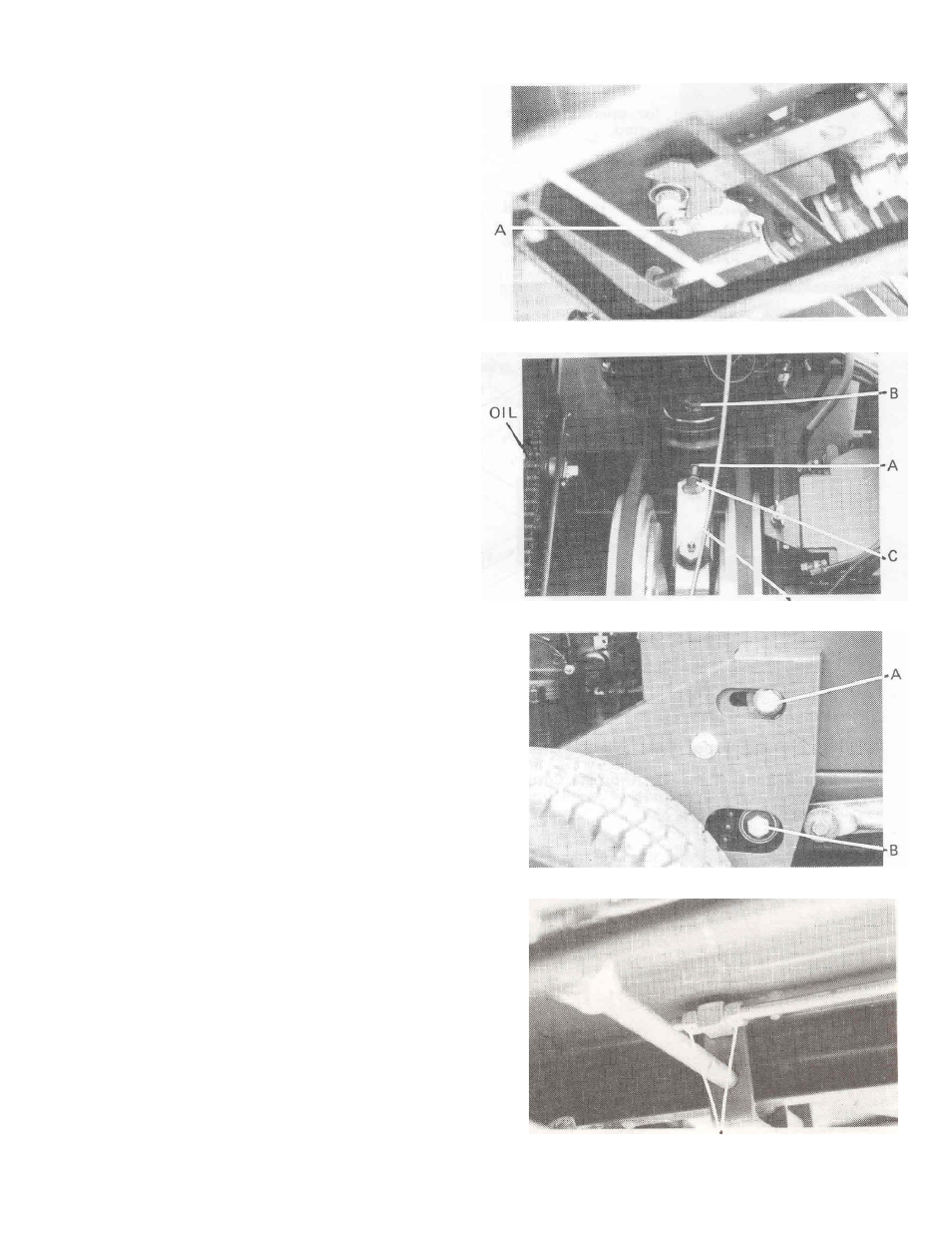
1.
Loosen locknut (A) Fig.22
2.
Centralise engagement lever (D) with friction plates
between drive pulleys, Fig.23
3.
Re-tighen locknuts (A), Fig.22
CONTINUOUS BELT
This can be adjusted as follows:-
1.
Loosen locknut (A) Fig.23
2.
Loosen pivot bolt (B) Fig.23
3.
Adjust belt tension using bolt (C) Fig.23
4.
Re-tighten locknut (A) and pivot bolt (B)
NOTE
: Belt to have 5mm deflection with finger pressure
between return pulley and drive pulley.
DRIVE CHAIN ADJUSTMENTS
Primary
1. Loosen off bolt ‘A’ Fig.24
2. Slide idler back till chain tightens
3. Re-tighten bolt ‘A’ and check chain for tight spots
Secondary
1. Loosen off bolt ‘B’ Fig.24
2. Slide sprocket back till chain tightens
3. Re-tighten bolt ‘B’ and check chain for tight spots
CAUTION
: Do not over-tension belts or drive chains.
DRIVE SELECTOR PEDAL
The pedal angle can be tilted either forward on back to suit
individual requirements if necessary.
1.
Loosen locknuts (A) on control rod Fig.25
2.
Tilt control pedal to required angle to give maximum
operator comfort.
3.
Retighten locknuts
Fig. 22
Fig. 23 D
Fig. 24
Fig. 25 A
10