Router mounting, Operation – Ryobi 4950301 User Manual
Page 12
Page 12
ROUTER MOUNTING
around the raised portion on the underside of the
accessory table, clamping it tightly against the rear
rail.
■
Secure with a 5/16 in. washer and 5/16-18 x 3/4 in.
knob bolt.
■
Tighten knob bolt securely.
FINAL ASSEMBLY:
After the router mounting parts have been assembled,
your setup should be similar to
Figure 13.
■
Compare your setup and make any necessary
adjustments.
■
Recheck all knob bolts, attachments, etc., and
securely tighten.
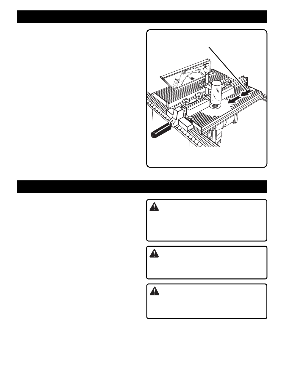
Fig. 13
DIRECTION OF FEED IS FROM RIGHT TO LEFT
AGAINST SHARP EDGES OF ROTATING BIT
ROUTER KIT SHOWN COMPLETELY ASSEMBLED
WARNING:
The direction of feed for the workpiece is always
against the sharp edges of the bit and into the
rotation of the cutter. Failure to heed this warning can
result in serious personal injury.
WARNING:
Do not use the guide fence with ball-bearing piloted
bits. Failure to heed this warning can result in serious
personal injury.
WARNING:
The guard/dust cover must be used in all routing
operations. Do not attempt freehand use on
workpieces larger than 6 in. (15 cm) in diameter.
OPERATION
FINAL PREPARATION FOR OPERATION
See Figure 13.
■
Adjust dust cover so that it will not come in contact
with workpiece during a cutting operation.
■
Direction of feed of workpiece is from right to left as
shown by the arrows in figure 13.
■
The workpiece must always
be tight against the
guide fence, unless a ball bearing piloted bit is being
used. The infeed fence should be adjusted to support
the uncut workpiece while the outfeed fence should
be adjusted to properly support the workpiece after
the cut passes the router bit, compensating for the
removed stock.