Tremely easy to wire, Hydronic boiler water heater, 120vac wiring center – Raypak XFYRE 500 User Manual
Page 6: Low voltage wiring center
6
X
tremely Easy to Wire
300
28
17
19
8
14
5
14
5
40
36
28
16
400
38
18
25
7
19
4
19
4
40
47
29
16
500
47
16
31
7
24
4
24
4
40
56
23
17
700
66
30
44
13
33
7
33
7
40
70
34
19
850
80
40
53
17
40
9
40
9
40
80
40
20
XFyre
Model
20°F
GPM
DT
40°F
30°F
Minimum Flow*
Rates Of Flow And Pressure Drops
300
1711
1140
855
684
570
489
428
380
342
400
2275
1517
1138
910
758
650
569
506
455
500
2851
1901
1426
1140
950
815
713
634
570
700
3992
2661
1996
1597
1331
1140
998
887
798
850
4847
3231
2423
1939
1616
1385
1212
1077
969
Temperature Rise (°F)
XFyre
Model
100
80
90
60
70
40
50
30
20
Recovery Rates
300
30
19
8
1.5
10
24
24
17
1.5
19
400
30
25
7
2
8
20
38
18
2
21
500
30
31
7
2
8
20
47
16
2
20
700
30
44
13
2
17
20
66
30
2
38
850
32
51
16
2
20
24
67
28
2
36
Soft
(0-4 Grains Per Gallon)
Water Hardness
Hard
(16-25 Grains Per Gallon)
Medium
(5-15 Grains Per Gallon)
XFyre
Model
Maximum Flow
GPM
DT
*Closed systems only
DP
DP
GPM
DP
GPM
DP
GPM
DP
DT
DP MTS
DT
GPM
SHL
GPM
MTS
DP
SHL
Do not use when hardness
exceeds 15 grains per gallon
MTS = Minimum Tube Size, inch.
SHL = System Head Loss, ft (based on heater and tank placed no more than 5 ft apart).
DT = Temperature rise, °F
DP = Pressure drop through heat exchanger, ft
Hydronic Boiler
Water Heater
DT GPM
MTS
DP
SHL
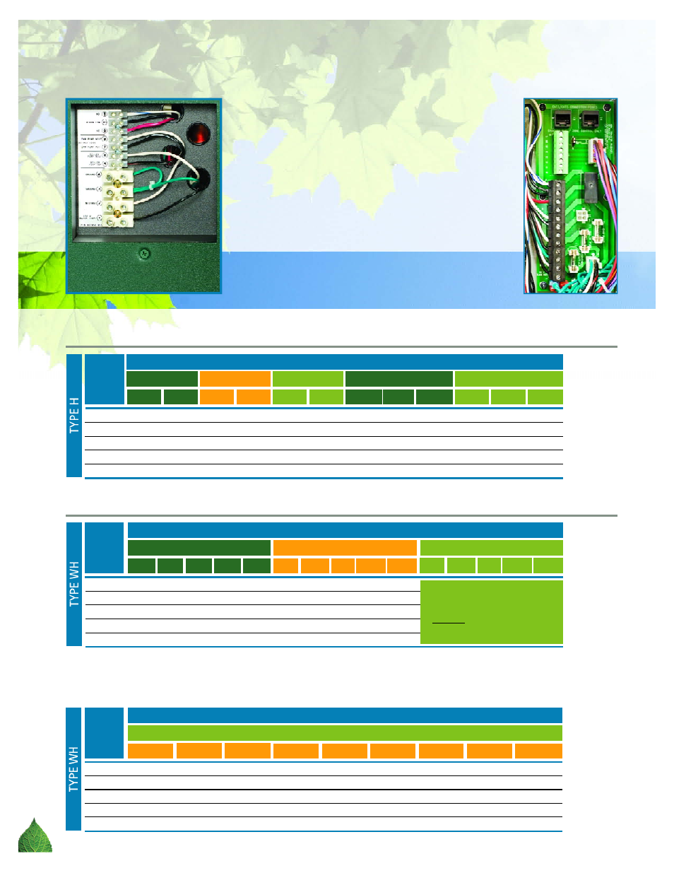
120VAC Wiring Center
The XFyre’s 120VAC wiring center is located on the rear
of the boiler. All incoming line voltage and pump wiring
are contained away from the 24v control wiring. Wiring
the boiler is simple and straight forward.
Low Voltage Wiring Center
Just like its big brother the XTherm, the XFyre has a
separate front mounted wiring center for all of the
low voltage connections. This makes thermostat, water
sensor, 0-10VDC BMS, and alarm contacts a breeze to
set up. No more guessing where the contact points
are buried in the boiler. Built-in cascade control using
CAT 3 or CAT 5 computer network patch cables to
connect with the communication bus between boilers.
Simply remove the front door for quick access.
120VAC Wiring Center
(rear of boiler)
Low Voltage
Wiring Center