4 connection with a user system – Renesas R0E001000EXT00 User Manual
Page 2
R0E001000EXT00 User’s
Manual
R0
E53
065
0M
CU
00
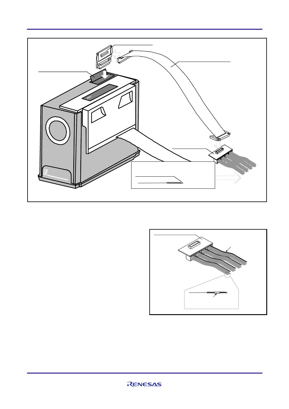
R0E001000EXTE0
R0E001000FLX10
flexible cable
R0E001000EXTT0
External trigger connector
(1)
User-system connection sockets
(204351-1 made by AMP)
Size: 0.76 mm
(2)
(3)
(4)
100
HIGH PER
FORMANC
E
EMULATO
R SYSTEM
Figure 2 Usage of the R0E01000EXT00
4 Connection with a User System
(See Figure 3)
REJ10J1817-0200 Rev.2.00
Page 2 of 4
Apr 16 2010
(1) GND connection
The black wire connected to the R0E001000EXTT0
board acts as a GND terminal. This wire must be
connected to GND of the user system.
(2) Trigger-signal correspondence table
Input and output attributes for trigger signals are
specifiable through settings in the emulator debugger.
Table 1 shows the correspondence between the [Trigger]
section ([External trigger cable]) on the [System] page of
the [Configuration Properties] dialog box of the emulator
debugger and identification numbers for the user-system
connection sockets.
Wires:
Black (GND) and gray (signal)
Identification number on the sticker
for each user-system connection socket
R0E001000EXTT0
Figure 3 Connection with a User System