页面 6 – Reliable MSK-1341B User Manual
Page 7
15.T h r e a d t ake-up s p r i n g (fig. 1 3 )
1. Ad ju st in g th e th re ad ta ke -u p sp ri ng st ro ke
a. Lo os en th e sc re w
,a nd mo ve th e di sc le ft wa rd
or ri gh tw ar d;
b. Mo ve th e di sc ri gh tw ar d to in cr ea se th e sp ri ng
st ro ke ,c on tr ar y, to de cr ea se th e sp ri ng st ro ke .
2. Ad ju st in g th e te ns io n of th re ad ta ke -u p sp ri ng
Ti gh te n th e nu t ,t ur n th e sp ri ng sh af t co un te r-
co lc kw is e to in cr ea se th e te ns io n, co tr ar y, to de cr ea se
th e te ns io n. Pl ea se us e a sc re wd ri ve r to ro ta te th e sp ro ng
sh af t to ge t th e re qu ir ed te ns io n.
①
②
③
④
⑤
16.A d j u s ting t he p re s s u r e o f p resser f o o t ( F ig.14 )
Adj ust the pre sse r foo t pre ssu re acc ord ing to the mat er-
ial s.( the sta nda rd hei ght of pre ssu re adj ust men t scr ew
is 25m m).
1.T urn the scr ew
clo ckw ise (A dir ect ion )to inc rea se
the pre ssu re, con tra ry, tur n the scr ew
cou nte r-
clo ckw ise (B dir ect ion )to dec rea se the pre ssu re,
2.A fte r the pro per pre ssu re is got ,ti ght en the nut
.
①
①
①
②
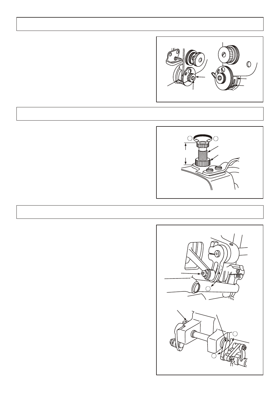
17.A d j u s ting t he h ei g h t o f p r e sser f oot ( f i g .15)
1.Th e optimum fixed position of presser foot is to adjust
Th e presser foot to the “1/8”indication line on
Th e feed crank.
Loosen the nut
and adjust the cam link assembl ing
position.
a.At he highest position A, the max .Pr esser foot
Vertical stroke is got;
b.At the lowe st position B, the mi n. Pr esser foot
vertical stroke is got.
2.Us ually, the srtoke of outer presser foot is same as that of
the inner presser foot.
A. Loosen the screw
;
b.When the thread take-up lever is at its highest
position,lay down the presser bar lever;
c.Ad just the feed crank
to leftwa rd(A directon)
to increase the presser foot stroke.contrary,adjust
the feed crank
to rightwa rd (b direction) to
decrease the presser foot stroke.
①
②
③
③
①
②
③
④
⑤
Standard
25mm
B
A
①
②
①
B
AA
A
②
③
B
A