Figure 3-11 . rs-232 control system connection, Vhd controller, 11. rs-232 control system connection – Runco Vision 85 User Manual
Page 40: Pre l iminar y
28
Vidikron Vision 85 Owner’s Operating Manual
PRE
L
IMINAR
Y
Connecting a PC or
Automation System to the
VHD Controller
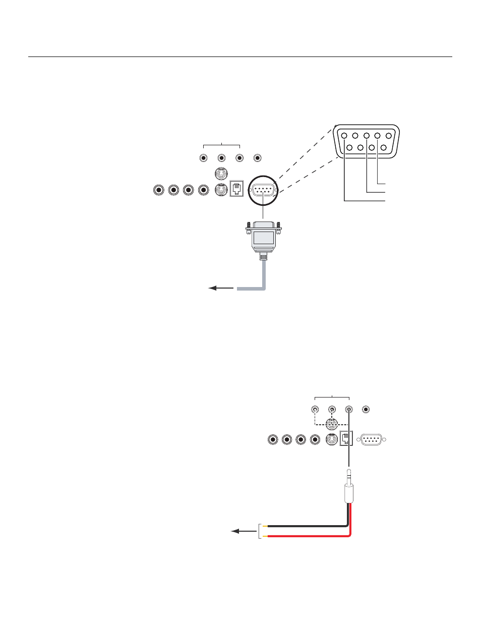
Use a standard, 9-pin RS-232 cable to connect a PC or home theater control/automation
system (if present) to the RS-232 Control port on the VHD Controller; see Figure 3-11.
For more information about using this connection, refer to Serial Communications on
page 67.
Figure 3-11. RS-232 Control System Connection
Connecting 12-Volt Trigger
Outputs to External
Equipment
VHD Controller: If your home theater contains equipment that responds to 12-volt triggers
(such as a retractable screen or screen mask), connect them to the 12-volt trigger outputs of
the VHD Controller as shown in Figure 3-12.
For more information on using the VHD Controller triggers, refer to Triggers on page 51.
Figure 3-12. 12-volt Trigger Output Connections (from VHD Controller)
➤
Pb
Pr
Y
Video
3
IR
RS-232 Control
S-Video 1
S-Video 2
1
2
TRIGGERS
RS-232 Out
Component Video
1
2
3
4
5
7
8
9
6
to Automation/
Control System
or PC
2 Transmit Data
3 Receive Data
5 Ground
(none of the other pins are used)
➤
Pb
Pr
Y
Video
3
IR
RS-232 Control
S-Video 1
S-Video 2
1
2
TRIGGERS
RS-232 Out
Component Video
to other,
12-volt
trigger-activated equipment
(screen, screen mask etc.)
Tip = +12V
Sleeve = Ground
3.5-mm
mini plug