Description 2. package components, 2/3) 4. application, External dimensions of m3t- flx-dct613 – Renesas M3T-FLX-DCT613 User Manual
Page 2: Connection procedure, Bc d 45.0, Specifications
1. Description
2. Package Components
(see Figure 1)
(1)
M3T-
FLX-DCT613 conversion board
Figure 1 Package components of
M3T-
FLX-DCT613
M3T-
FLX-DCT613 main unit
(2/3)
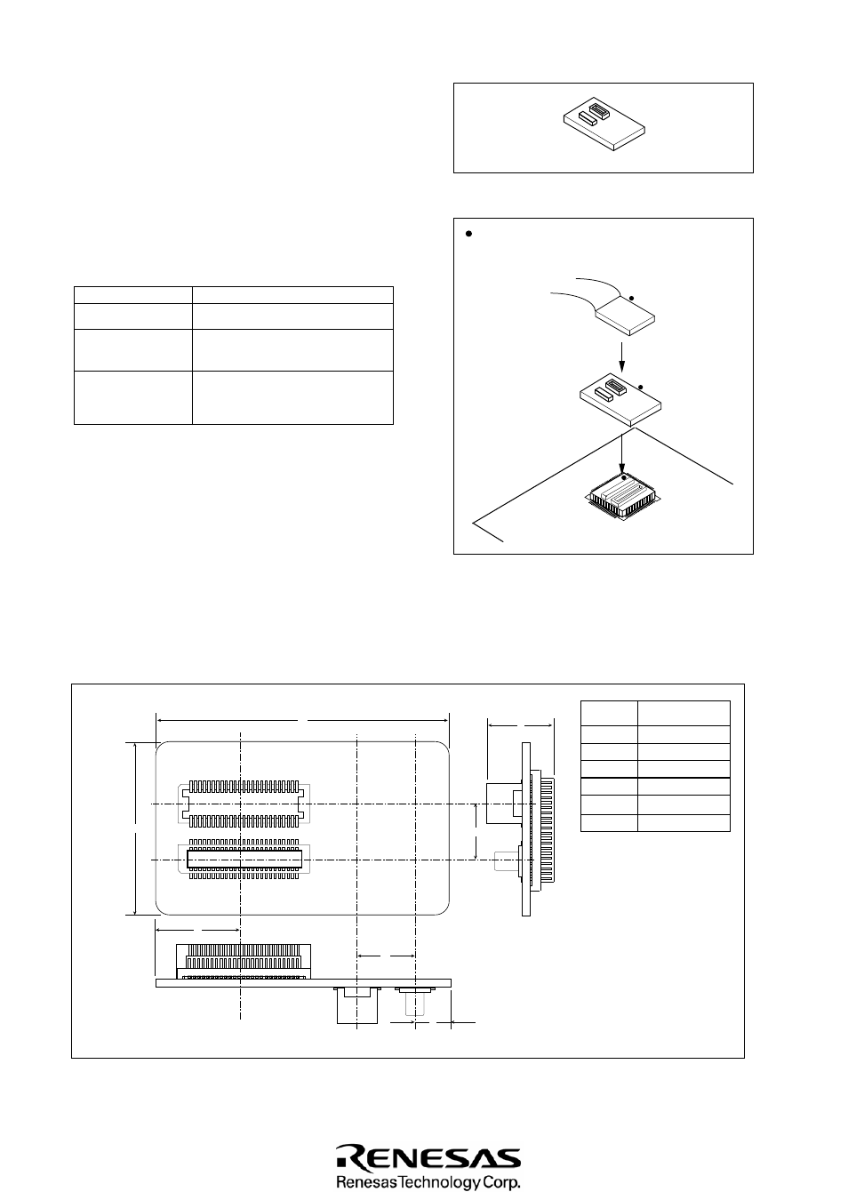
4. Application
(see Figure 2)
Use this converter when you have
M3T-
DIRECT80S (used
for 80
-pin 0.65mm-pitch QFP) mounted on the
target
system
and
want to connect an emulation pod for the M16C/60
Series
to the
target
system.
Figure 2 Usage of
M3T-
FLX-DCT613
6. External Dimensions of
M3T-
FLX-DCT613
: position of No. 1 pin
Be sure to match the position of
No. 1 pin of the foot pattern and
each part.
(2)
M3T-
FLX-DCT613 Instruction Manual (this manual)
M3T-
DIRECT80S
M3T-
FLX-DCT613
5. Connection Procedure
(see Figure 2)
(1)
(2)
(3)
(1) Mount the
M3T-
DIRECT80S to the target system.
(2) Connect the
M3T-
FLX-DCT613 and the emulation
pod for M16C/60, 61 series MCUs.
(3) Connect the
M3T-
DIRECT80S and the
M3T-
FLX-DCT613.
Figure 3 External dimensions of
M3T-
FLX-DCT613
M3T-
FLX-DC
T
613 REV.A
A
Symbol
B
C
D
45.0
10.0
9.0
10.0
E
M
6.3
25.0
50
26
1
25
50
26
1
25
J1
J2
MADE IN JAPAN
A
M
E
C
B
D
M
This converter connects an emulation pod for the M16C/60
Series to the connector provided at the top of the direct
dummy IC,
M3T-
DIRECT80S.
Emulation pod for
M16C/60, 61 Series
MCUs
80P6S-A
(80-pin 0.65mm-pitch QFP)
3. Specifications
Table 1 Specifications
Item
Description
Package
Applicable MCU
M16C/60, 61 Series
Insertion/removal
iterations of
connector
20 times guaranteed
Dimension [mm]