Outline, Package components, Connection procedure – Renesas R0E33062PMSRC0 User Manual
Page 4: Caution
(2/4)
1. Outline
The R0E33062PMSRC0 is an emulation memory board for the M16C/60 Series compact emulator. The memory space can be
allocated to the emulation memory by using with the M16C/60 Series compact emulator M3062PT3-CPE etc.
2. Package Components
Table 1 Package Components
Item Quantity
R0E33062PMSRC0 emulation memory board
1
Spacers for fixing the emulation memory board
4
R0E33062PMSRC0 User’s Manual (this document)
1
R0E33062PMSRC0 User’s Manual (Japanese)
1
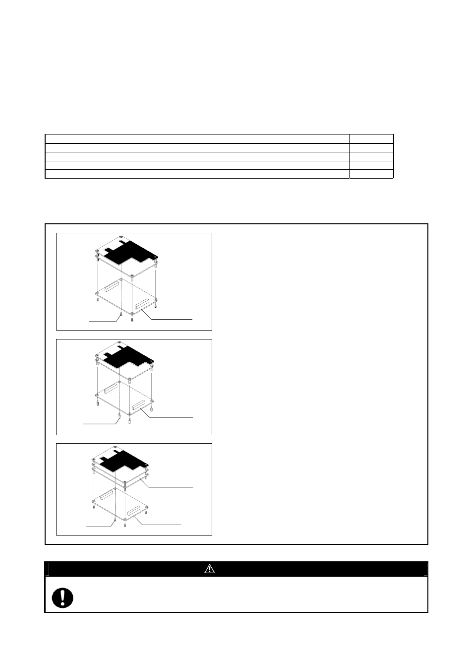
3. Connection Procedure
The procedure for connecting the R0E33062PMSRC0 is shown in Figure 1.
(1) Unscrew the four screws securing the emulation probe.
(2) Pull out the M3062PT2-EPBM from the compact emulator control
board (hereafter, upper board) vertically, otherwise the connectors
may be damaged.
(3) Attach connectors J1 and J2 of the new R0E33062PMSRC0 to
connectors J3 and J4 of the upper board, respectively.
(4) Tighten the spacers (included) in an even, crisscross pattern to
secure the R0E33062PMSRC0 with such as box wrench.
(5) Attach connectors J1 and J2 of the M3062PT2-EPBM to connectors
J3 and J4 of the R0E33062PMSRC0, respectively.
(6) Tighten the four screws (which are unscrewed in the procedure 1) in
an even, crisscross pattern to secure the M3062PT2-EPBM with a
screwdriver.
(7) After replacing the board, perform the self-check to make sure that
the R0E33062PMSRC0 has been installed properly.
Figure 1 Connecting procedure of the emulation memory board
CAUTION
Cautions to Be Taken for This Product:
z Before you replace the emulation memory board, shut off the power, otherwise internal circuits may be damaged.
z Insert or pull out the connectors vertically, otherwise the connectors may be damaged.
M3062PT2-EPBM
Screws
R0E33062PMSRC0
Spacers
M3062PT2-EPBM
R0E33062PMSRC0
Screws