Installing the storage tank, Temperature and pressure relief valve, Vacuum relief valve – Rheem Marathon Thermal MTS105200 User Manual
Page 6: Drain pan
6
A new combination temperature and pressure relief valve, complying with the Standard for Relief
Valves and Automatic Gas Shut-Off Devices for Hot Water Supply Systems, ANSI Z21.22, is supplied
and must be installed in the opening provided and marked for the purpose on the storage tank. No
valve of any type should be installed between the relief valve and the tank. Local codes shall govern the
installation of relief valves.
!
WARNING: The
pressure rating of the
relief valve must not
exceed 150 PSI, the
maximum working
pressure of the storage
tank as marked on
the rating plate.
Temperature and Pressure Relief Valve
Connect the outlet of the relief valve
to a suitable open drain so that the
discharge water cannot contact live
electrical parts or persons and to
eliminate potential water damage.
Piping used should be of a type
approved for hot water distribution.
The discharge line must be no smaller
than the outlet of the valve and must
pitch downward from the valve to
allow complete drainage (by gravity)
of the relief valve and discharge line.
The end of the discharge line should
not be threaded or concealed and
should be protected from freezing.
No valve of any type, restriction or
reducer coupling should be installed in
the discharge line.
Vacuum Relief Valve
NOTICE: Do NOT
remove or tamper with
the vacuum relief valve for
any reason. Doing so will
void the manufacturer’s
warranty.
The vacuum relief valve, which must
be used when installing the storage
tank, is factory installed.
The cold water inlet has a vacuum
relief valve installed. Certain
conditions in the field may produce a
vacuum or negative pressure condition
inside the storage tank. This negative
pressure can cause the tank to fail.
The vacuum relief valve provides
a means to eliminate the negative
pressure or vacuum by admitting air
into the tank to equalize the pressure.
It is not recommended to pull a
vacuum on the unit.
If a vacuum is pulled on the unit,
refer to the "To Fill the Storage tank"
section to ensure the unit is full of
water before operating.
Installing the storage tank.
NOTICE: Auxiliary
catch pan MUST
conform to local
codes.
The storage tank should not be
located in an area where leakage of
the tank or connections will result in
damage to the area adjacent to it or
to lower floors of the structure. It is
recommended that a suitable catch
pan, adequately drained, be installed
under the storage tank.
Catch pan kits are available from
the store where the storage tank
was purchased, or any water heater
distributor.
Under no circumstance will the
manufacturer be held liable for any
water damage in connection with this
storage tank.
■■■✦■■■
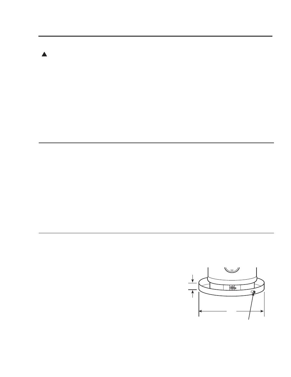
B
A
To open drain, this line should be at least 3/4
s ID and
pitched for proper drainage.
B = Max 2
s
A = Diameter of
storage tank
plus 2
s min.
Drain Pan