Connection procedure (see figure 3), External dimensions and a sample foot pattern – Renesas R0E53032ACSJC0 User Manual
Page 2
R0E53032ACSJC0 User’s
Manual
5. Connection Procedure (See Figure 3)
REJ10J1878-0200 Rev.2.00
Page 2 of 4
Apr 16, 2010
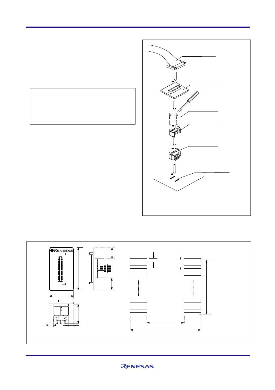
The procedure for connecting the R0E53032ACSJC0 is shown
below.
(1) Mount the NSPACK20BG on the user system.
(2) Attach the YSPACK20BG on the NSPACK20BG.
(3) Secure the four corners of the YSPACK20BG with the
YS–GUIDEs.
● Do NOT use the screws included with the
YSPACK20BG for fixing the YSPACK20BG.
● Do NOT use the screwdriver included with the
NSPACK20BG for fixing the YS–GUIDEs. That is
used only for the HSPACK20BG.
(4) Mount the R0E53032ACSJC0 on the YSPACK20BG.
(5) Attach the flexible cable R0E001000FLX10 of the
emulator to the R0E53032ACSJC0.
(1)
(2)
(3)
(4)
(5)
Use a slotted screwdriver.
●: No.1 pin
Be sure to align the pins.
20-pin 0.65mm pitch
foot pattern
NSPACK20BG
YSPACK20BG
YS-GUIDE (×2)
Flexible cable
R0E001000FLX10
R0E53032ACSJC0
Figure 3 Connection procedure of the R0E53032ACSJC0
6. External Dimensions and a Sample Foot Pattern
16
.5
0
22.00
38
.00
4.50
10
.5
5
4.50
10
.5
5
CN1
1
50
51
100
TP1
TP2
R0E53032ACSJC0
REV.A
M
A
D
E
I
N
J
A
P
A
N
P
b F
ree
4.30
7.30
5.
8
5
Unit: mm
0.35
0.65
Figure 4 External dimensions and a sample foot pattern of the R0E53032ACSJC0