Assembly – Ryobi RT501W User Manual
Page 11
ASSEMBLY
11
Fig. 3
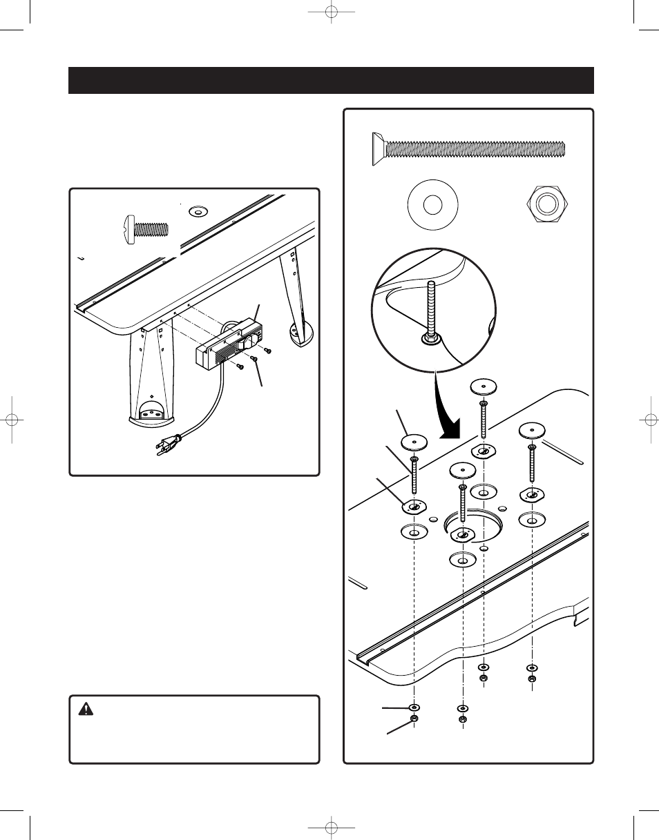
TO ATTACH THE SWITCH BOX
See Figure 3
4. Place the router table on its legs.
5. Use a #2 Phillips screwdriver to attach switch box (G) to
the switch box bracket with 3 self tapping screws (AF).
To attach screws, washers and nuts for
mounting router
See Figure 4
6. Place the 4 flange nuts (U) in the 4 countersink holes of the
tabletop.
7. Insert the 4 countersink screws (AC) through holes in table
top. Tighten securely with the 4 hex nuts (AD) placing the
4 washer (AE) between the nuts (AD) and the tabletop.
Use an adjustable wrench or a combination wrench
(size 10 mm) to tighten the nuts (the detail in figure 4
shows the finished assembly).
8. Press the 4 caps (K) to cover the heads of the
countersink screws.
NOTE:
Press the caps down until they are flush with table
top.
AF (3)
G
AF
AC (4)
AD (4)
AE (4)
Fig. 4
AC
K
AE
U
AD
CAUTION:
If you choose not to use the universal router mounting
system, simply remove the associated hardware (AD,
AE, U, AC)
, but keep the caps (K) in place.
Bdal 6146.461 3Sprachen 04.06.2005 11:58 Uhr Seite 11