Outline, Package components, Specifications – Renesas Converter Board M3T-100LCC-QSD User Manual
Page 4: Usage, Package components (see figure 1), Usage (see figure 2)
( 2 / 4 )
1. Outline
The M3T-100LCC-QSD is a converter board for connecting
100-pin 0.65-mm-pitch LCC (100D0) to 100-pin 0.5-mm-
pitch LQFP (100P6Q-A or 100P6D-A).
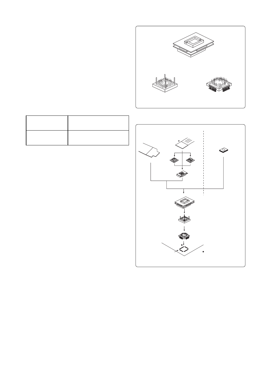
2. Package Components (See Figure 1)
(1) M3T-100LCC-QSD ................................................... x1
(2) TQSOCKET100SDG
(Tokyo Eletech Corporation) .............
x1
(3) TQPACK100SD
(Tokyo Eletech Corporation) ......................
x1
(4) M3T-100LCC-QSD User's Manual (This manual)
3. Specifications
Table 1 Specifications
4. Usage (See Figure 2)
The M3T-100LCC-QSD can be used for debugging and
onboard evaluation in common.
(1) For debugging
Mount the TQPACK100SD on the foot pattern of the
target system. And mount the TQSOCKET100SDG and
M3T-100LCC-QSD on it. Then attach the cable of the
emulator to the upper IC socket of the M3T-100LCC-
QSD.
(2) For onboard evaluation
Mount an MCU with EPROM (100D0) on the upper IC
socket of the M3T-100LCC-QSD.
Before using the M3T-100LCC-QSD, be sure to read "7.
Precautions" on page 4.
Figure 2 Usage of the M3T-100LCC-QSD
Applicable package
Insertion/removal
iterations of IC socket
100P6Q-A or 100P6D-A
(100-pin 0.5-mm-pitch LQFP)
20 times guaranteed
(1) Debugging
Cable for 100LCC
MCU (100D0)
FLX100 cable
M3T-FLX100-T
M3T-FLX100-R
M3T-FLX100LCC
M3T-100LCC-QSD
TQSOCKET100SDG
TQPACK100SD
100-pin 0.5-mm-pitch
(100P6Q-A or 100P6D-A)
foot pattern
: No. 1 pin position
Be sure to align the pins.
(2) Onboard evaluation
(1) M3T-100LCC-QSD main unit
(2) TQSOCKET100SDG
(3) TQPACK100SD
Figure 1 Package component of the M3T-100LCC-QSD