Gas inserts, Clearances, Combustible mantels – Regency Gas Insert E33-NG1 User Manual
Page 2
Clearances
Unless otherwise stated the clearances listed below are Minimum
distances to combustible materials. Please Note: A major cause
of chimney related fi res is due to a failure to maintain required
clearances (air space) to combustible materials. It is of the greatest
importance that this fi replace and vent system be installed only in
accordance with these instructions.
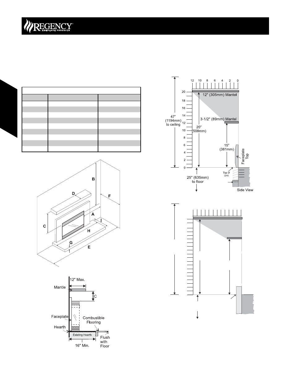
Combustible Mantels
Because of the extreme heat this fi replace emits, the mantel
clearances are critical. Combustible mantel clearances from top of
the louvers are shown in the diagram below. Mantel may be installed
anywhere in the shaded area or higher.
Note: A non-combustible mantel may be installed at a lower
height.
Note: Ensure the paint that is used on the mantel and the facing
is “heat resistant” or the paint may discolour.
Clearances to Combustibles
Dimension
Description
E33
A*
From Unit to Side Walls
8” (203mm)
B
From Unit to Ceiling
47” (1194mm)
C
Minimum Mantel Height
15” (381mm)
D
Maximum Mantel Depth
12” (305mm)
E
Alcove Width
76” (1930mm)
F
Alcove Depth
36” (914mm)
G
Hearth Height
1-¼” (32mm)
H
Hearth Width
45-½” (1156mm)
I
Hearth Depth
13” (330mm)
* Alcove side wall must have a minimum of 8” (203mm) clearance on one side.
25" (635mm)
to floor
Side View
12" (305mm) Mantel
3-1/2" (89mm) Mantel
20”
(508mm)
47”
(1194mm)
to ceiling
15”
(381mm)
2
0
12
6
4
8
10
2
0
12
6
16
4
14
8
18
20
10
Top of
Unit
Flush Front Mantel Clearances
Full Screen Door Mantel Clearances
E33 Gas Insert
D
128
June 2007 Regency Product Specifi cations Book
Gas Inser
ts
Gas Inserts